


MultiProcessor Specification
4-14 Version 1.4
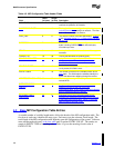
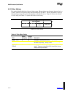
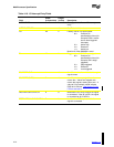
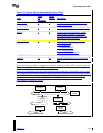
Table 4-10. I/O Interrupt Entry Fields
Field
Offset
(in bytes:bits)
Length
(in bits) Description
ENTRY TYPE 0 8 Entry type 3 identifies an I/O interrupt
entry.
INTERRUPT TYPE 1 8 See Table 4-11 for values.
PO 2:0 2 Polarity of APIC I/O input signals:
00 = Conforms to
specifications of bus (for
example, EISA is active-
low for level-triggered
interrupts)
01 = Active high
10 = Reserved
11 = Active low
Must be 00 if the 82489DX is used.
EL 2:2 2 Trigger mode of APIC I/O input signals:
00 = Conforms to
specifications of bus (for
example, ISA is edge-
triggered)
01 = Edge-triggered
10 = Reserved
11 = Level-triggered
SOURCE BUS ID 4 8 Identifies the bus from which the interrupt
signal comes.
SOURCE BUS IRQ 5 8 Identifies the interrupt signal from the
source bus. Values are mapped onto
source bus signals, starting from zero. A
value of 0, for example, would indicate
IRQ0 of an ISA bus. See Section D.3 for
PCI bus semantics.
DESTINATION I/O APIC ID 6 8 Identifies the I/O APIC to which the signal
is connected. If the ID is 0FFh, the signal
is connected to all I/O APICs.
DESTINATION I/O APIC INTIN# 7 8 Identifies the INTIN
n
pin to which the
signal is connected.