


Default Configurations
Version 1.4 5-7
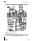
Certain EISA chipsets do not bring out the IRQ0, 8254 timer interrupt, and IRQ13 EISA DMA
chaining interrupt signals. If these signals are not directly available, INTIN2 and INTIN13 should
be disabled. Refer to Section 5.3.1 for more details.
5.3.1 EISA and IRQ13
IRQ13 is a shared interrupt as defined in the EISA bus specification. Because a compliant system
supports only the on-chip floating point unit, IRQ13 carries only the EISA chaining interrupt.
If IRQ13 is not connected to the I/O APIC, the EISA chaining interrupt may be handled as a
mixed-mode operation. Mixed mode means that the APIC and 8259A-equivalent PIC are
connected in a cascading manner via INTIN0, and INTIN0 is programmed for ExtINT and edge-
triggered mode. If all other interrupts are masked off in the PIC, INTIN0 only receives the DMA
chaining interrupt.
An MP operating system should disable the I/O APIC INTIN13 and configure the I/O APIC to
mixed mode if the EISA DMA chaining signal is not available at the I/O APIC.
5.3.2 Level-triggered Interrupt Support
Several AT-compatible buses, such as EISA and MCA, support active-low, level-triggered
interrupts. If these types of buses are to be incorporated in a compliant system, external inverters
must be implemented to ensure that signals presented to the 82489DX APIC are active-high and
level-triggered. See Section 4.3.4 on I/O Interrupt Assignment Flags.
For EISA implementations, the external interrupt polarity control inverters must be controlled by
the EISA edge/level-triggered polarity control registers (4D0h-4D1h). MCA does not have this
register. To convert an active-high trigger to an active-low trigger, an inverter for each interrupt
line must be implemented.
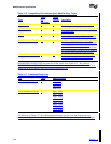
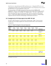
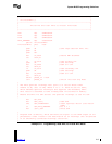
5.4 Assignment of System Interrupts to the APIC Local Unit
The APIC local unit has two general-purpose interrupt inputs that are reserved for system
interrupts. Table 5-3 shows how the interrupt request line (IRQ) assignments are connected to the
local APIC in each of the default configurations.
Table 5-3 Assignment of System Interrupts to APIC Local Unit
All Local
APICs
LINTINx
Config
1
Config
2
Config
3
Config
4
Config
5
Config
6
Config
7 Comments
LINTIN0 8259A
INTR
8259A
INTR
8259A
INTR
8259A
INTR
8259A
INTR
8259A
INTR
8259A
INTR
INTR output from
master 8259A or
equivalent
LINTIN1 NMI NMI NMI NMI NMI NMI NMI Nonmaskable
interrupt