


MP Configuration Table
Version 1.4 E-5
Since all device settings must fall within supported System Address Space mapping for a given bus
in order to be usable by the operating system, buses that do not support dynamically configurable
devices (i.e., ISA, EISA) should support all possible addresses to that bus.
In general, the MP configuration table must provide entries to describe system address space
mappings for all I/O buses present in the system. There are two exceptions to this rule:
1. For buses that are connected via PCI-to-PCI-bridge-specification-compliant bridges: in this
case, the system address space mappings for such buses may be omitted from the configuration
table if bus hierarchy entries for these buses are also omitted (refer to Section 4.
4
.2 for
addit
ional information)
. In such cases, the operating system is expected to discover the address
space mapping by querying the PCI-to-PCI-bridge-specification-compliant bridge directly.
2. For buses that are connected via a parent I/O bus and for which the subtractive decode bit is set
(refer to Section 4.4.2 for details).
Typically, this would mean that a minimal description of resources allocated to PCI buses in a
system need only include System Address Space Mapping entries for PCI bus zero and any
additional peer PCI buses (if present) where these buses are connected by PCI bridges that are
specific to the chipset or host bus.
Note
System Address Mappings are unidirectional in nature. They only describe system addresses that
propagate to the target bus from any given processor. For DMA support on the target bus, all memory
addresses that contain real memory should be accessible directly by either the bus or by a bus-specific
DMA controller. For buses with fewer than 32-bit address lines, all real memory at addresses that the
bus can generate must be accessible for DMA.
4.4.2 Bus Hierarchy Descriptor Entry
If present, Bus Hierarchy Descriptor entries define how I/O buses are connected relative to each
other in a system with more than one I/O bus. Bus Hierarchy Descriptors are used to supplement
System Address Mapping entries to describe how addresses propagate to particular buses in
systems where address decoding cannot be completely described by System Address Space
Mapping entries alone.
In general, e
ntries of this type are required for each bus that is connected to the system
hierarchically below another I/O bus. The one exception to this is for PCI buses that are connected
behind a
PCI to PCI bridge specification compliant bridge. In this case the bus hierarchy entry
may be omitted as the operating system is expected to discover such buses without the need to refer
to the
configuration table.
Since bus hierarchy
descriptor
and system address space records are
intended to work in concert
,
the configuration table may chose to omit both types of records
for a
bus behind a compliant bridge or it may provide both. The table must not however provide one
without the other for buses behind
compliant bridges.
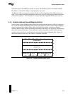
For example, given the system described in
Figure 4-10, bus hierarchy entries are required for the EISA bus and may be provided for
PCI
BUS 2 since both have parent buses that are themselves I/O buses. If the configuration table does
include
a bus hierarchy entry for PCI BUS 2, then
a complete set of
corresponding system address
space records must also be provided
.
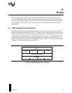
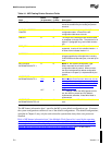
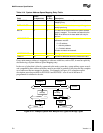
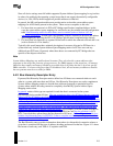
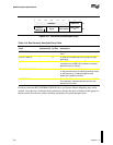
The Bus Hierarchy entry provides information about where in a hierarchical connection scheme a
given bus is connected and the type of address decoding performed for that bus. Figure 4-11 shows
the format of each entry, and Table 4-15 explains each field.