


Contents
viii
Figures
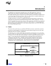
1-1. Conceptual Overview...................................................................... 1-1
1-2. Memory Layout Conventions .......................................................... 1-4
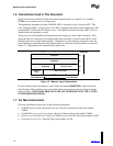
2-1. Multiprocessor System Architecture................................................ 2-2
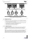
2-2. APIC Configuration ......................................................................... 2-3
3-1. System Memory Address Map........................................................3-2
3-2. PIC Mode....................................................................................... 3-8
3-3. Virtual Wire Mode via Local APIC................................................... 3-9
3-4. Virtual Wire Mode via I/O APIC..................................................... 3-10
3-5. Symmetric I/O Mode ..................................................................... 3-11
3-6. Multiple I/O APIC Configurations .................................................. 3-14
4-1. MP Configuration Data Structures .................................................. 4-1
4-2. MP Floating Pointer Structure......................................................... 4-3
4-3. MP Configuration Table Header...................................................... 4-5
4-4. Processor Entry............................................................................... 4-7
4-5. Bus Entry....................................................................................... 4-10
4-6. I/O APIC Entry............................................................................... 4-12
4-7. I/O Interrupt Entry ......................................................................... 4-13
4-8. Local Interrupt Entry...................................................................... 4-15
4-9. System Address Space Entry ....................................................... 4-18
4-10. Example System with Multiple Bus Types and Bridge Types ....... 4-19
4-11. Bus Hierarchy Descriptor Entry..................................................... 4-21
4-12. Compatibility Bus Address Space Modifier Entry.......................... 4-23
5-1. Default Configuration for Discrete APIC.......................................... 5-3
5-2. Default Configuration for Integrated APIC....................................... 5-5
Tables
1-1. Document Organization .................................................................. 1-3
3-1. Memory Cacheability Map............................................................... 3-3
3-2. APIC Versions................................................................................. 3-6
4-1. MP Floating Pointer Structure Fields .............................................. 4-3
4-2. MP Configuration Table Header Fields........................................... 4-6
4-3. Base MP Configuration Table Entry Types..................................... 4-7
4-4. Processor Entry Fields....................................................................4-8
4-5. Intel486™ and Pentium
®
Processor Signatures ............................. 4-9