


MP Configuration Table
Version 1.4 4-19
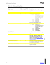
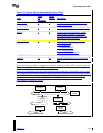
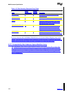
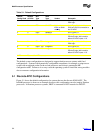
Table 4-14. System Address Space Mapping Entry Fields
Field
Offset
(in
bytes:bits)
Length
(in bits) Description
ENTRY TYPE 0 8 Entry type 128 identifies a System Address
Space Mapping Entry.
ENTRY LENGTH 1 8 A value of 20 indicates that an entry of this type
is twenty bytes long.
BUS ID 2 8 The BUS ID for the bus where the system
address space is mapped. This number
corresponds to the BUS ID as defined in the
base table bus entry for this bus.
ADDRESS TYPE 3 8 System address type used to access bus
addresses must be:
0 = I/O address
1 = Memory address
2 = Prefetch address
All other numbers are reserved.
ADDRESS BASE 4 64 Starting address
LENGTH 12 64 Number of addresses which are visible to the
bus
If any main memory address is mapped to a software visible bus, such as PCI, it must be explicitly
declared using a System Address Space Mapping entry.
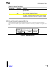
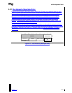
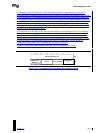
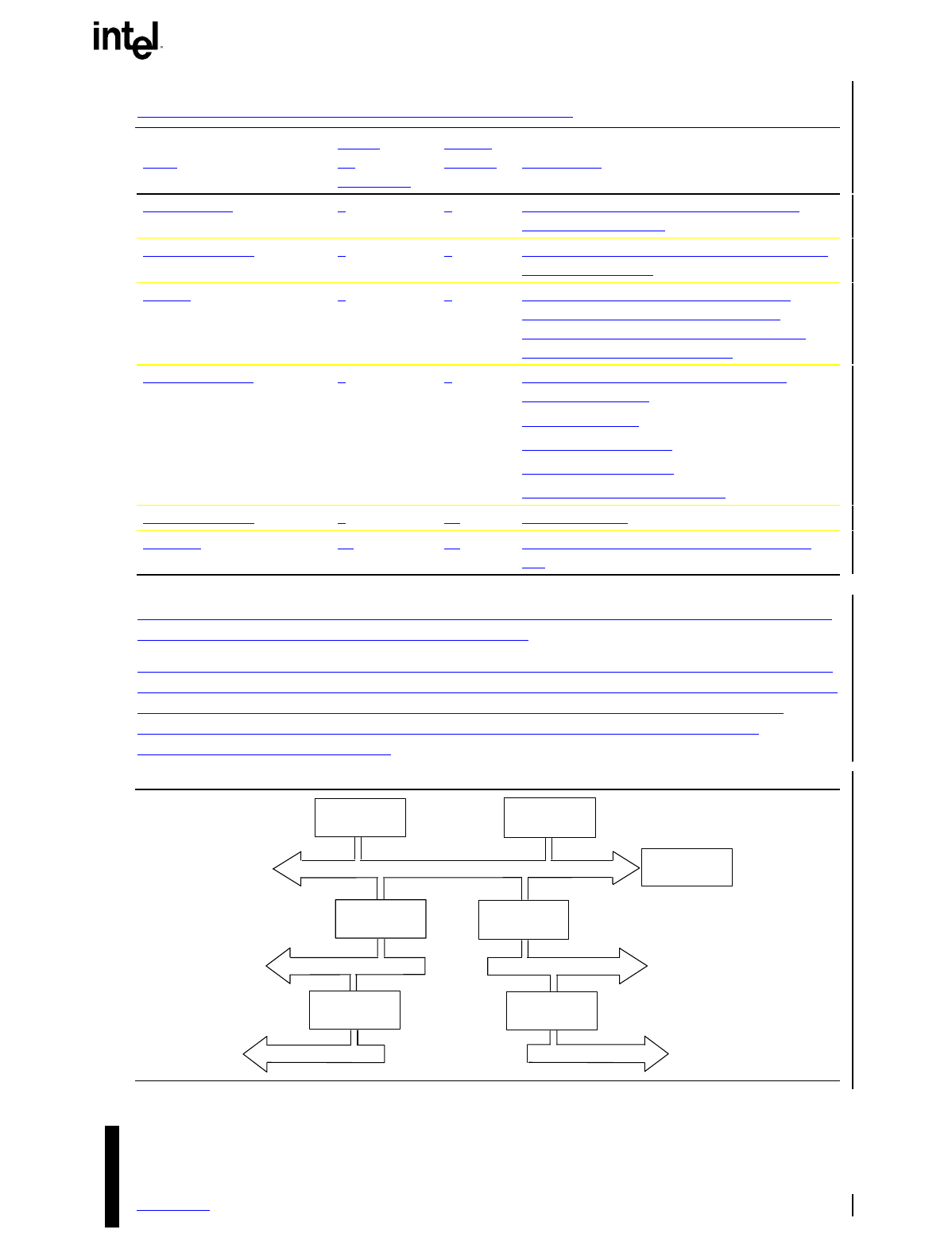
In the case of a bus that is directly connected to the main system bus, system address space records
and compatibility base address modifiers must be provided as needed to fully describe the complete
set of addresses that are mapped to that bus. For example, in Figure 4-10, complete explicit
descriptions must be provided for PCI BUS 0 and PCI BUS 1 even if one of the buses is
programmed for subtractive decode.
Processor 1
PCI Bus 1
EISA Bus
PCI Bus 2
Memory
Controller
EISA Bridge
Processor 0
System Bus
PCI
Host Bridge
PCI-to-PCI
Bridge
PCI Bus 0
PCI
Host Bridge