MultiProcessor Specification
5-4 Version 1.4
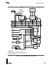
The INTA TRAP and GLUE in the figure are the additional hardware interface logic needed for the
82489DX APIC. INTA TRAP conditions all interrupt acknowledge cycles with ExtINTA to steer
the vector either from the 8259A PIC or the APIC. INTA TRAP is also responsible for preventing
the interrupt acknowledge cycle from reaching the 8259A PIC, in case ExtINTA is negated when
PINT is activated. During an interrupt acknowledge cycle with ExtINTA active, the APIC does
not return RDY#. Therefore, the ready generation logic should also take into consideration the
status of ExtINTA to steer the ready signal either from the APIC or from external bus logic,
depending upon the source of the interrupt vector.
The GLUE logic converts the INTR level-triggered interrupt output signal to a signal that is
acceptable to edge-triggered input pins, such as INTIN0 or LINTIN0.
If the AP used in these configurations does not automatically HALT after RESET or INIT, the AP
must be prevented from executing the BIOS by external hardware or by the BIOS itself.
5.2 Integrated APIC Configurations
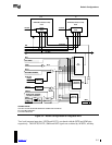
Figure 5-2 shows the default configuration for systems that use processors with the integrated
APIC, such as Pentium processors (735\90 or 815\100). The local APIC is configured as part of
the processor unit. The APICEN input is used to enable or disable the internal local APIC. If the
internal local APIC is used, the BIOS must initialize the APIC to Virtual Wire Mode during
system initialization.
Both Pentium processors used in the dual-processor (DP) system design are identical. The AP
functions exactly the same as the BSP processor, except that the AP will go to HALT after the
assertion of the RESET or INIT signals. It will remain halted until the MP operating system sends
a STARTUP IPI to bring it on line.


