


Front Panel I/O and Control Boards Intel® Server Platform
SR6850HW4 TPS
Revision 1.0
Intel order number D23151-001
88
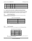
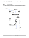
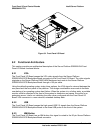
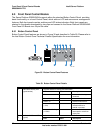
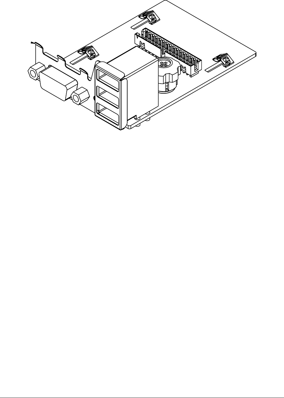
Figure 34. Front Panel I/O Board
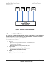
8.2 Functional Architecture
This section provides an architectural description of the Server Platform SR6850HW4 Front
Panel I/O Board functional blocks.
8.2.1 VGA
The Front Panel I/O Board passes the VGA video signals from the Server Platform
SR6850HW4 SCSI Backplane Board connector to the Front Panel I/O Board. The video signals
originate on the Server Platform E8500HW4 Mainboard and route to the Server Platform
SR6850HW4 SCSI Backplane Board through a 100-pin cable.
Using the default operating system video driver options, the VGA signal is mirrored between the
rear panel and the front panel of the platform. This design consideration was made to facilitate
user debug of an operating system hard failure. When the system is in a failure state, a portable
monitor could be attached to the front of the system to determine root cause. Since this is an
enterprise server, Intel is not validating the video driver configured with the Front Panel I/O
Board VGA connector in a non-mirrored, extended desktop state.
8.2.2 USB
The Front Panel I/O Board passes the high-speed USB 2.0 signals from the Server Platform
SR6850HW4 SCSI Backplane Board to the three USB ports on the front of the system.
8.2.3 NMI Button
The Front Panel I/O Board has an NMI button; this signal is routed to the 30-pin Server Platform
SR6850HW4 SCSI Backplane Board connector.