


System Overview Intel® Server Platform SR6850HW4 TPS
Revision 1.0
Intel order number D23151-001
12
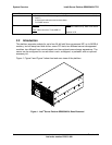
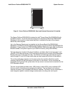
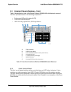
2.5.2 Server Board Set SE8500HW4 Memory Board
Each Memory Board supports the following features:
PCI Express x16 card edge connector that plugs into the Server Board Set
SE8500HW4 Mainboard
Intel E8500 chipset eXtended Memory Bridge (XMB)
Four DDR2 400HMz DIMM slots for registered ECC memory
Support for both single-rank and dual-rank DIMMs
Two DDR2 400MT/s busses
Independent Memory Interface (IMI), a high-speed differential bus
LED error indicators for each DIMM and an attention LED for hot-plug events
LED indicator for both memory mirroring and RAID configurations
Memory hot-plug at the card level, based on the PCI hot-plug model
Field Replaceable Unit (FRU) device
Two temperature sensors
Safety mechanism for instant power shut-down to the Memory Board when not
properly removed or inserted
See the Intel Server Board Set SE8500HW4 Technical Product Specification for
descriptions of this board.
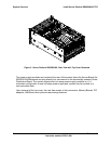
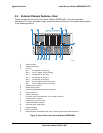
2.5.3 Power Distribution Board
The Power Distribution Board is located horizontally, below the Server Board Set
SE8500HW4 Mainboard in the middle-rear of the chassis. It has two connectors for the hot-
swap power supply modules and provides 12V, standby power and server management
signals to the Server Board Set SE8500HW4 Mainboard and SCSI Backplane Board. The
power distribution circuitry reports quantity, quality, and location of the installed power
supplies through I
2
C server management. See Chapter 6 for a description of this board.
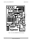
2.5.4 SCSI Backplane Board Board
The SCSI Backplane Board mounts vertically in the front of the system and contains ten
industry-standard hot-swap Single Connector Attach 2 (SCA-2) connectors (80-pin).
Ultra320 (or slower) Low Voltage Differential (LVD) SCSI hard disk drives can be installed in
the system. The backplane accepts 15,000-RPM (and slower) hard disk drives. Single-
Ended (SE) SCSI devices are not supported in the hot-swap hard disk drive bay.