


Intel® Server Platform SR6850HW4 TPS Cables and Connectors
Revision 1.0
Intel order number D23151-001
33
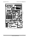
4.1 Cable and System Interconnect Descriptions
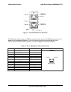
Table 7 and Table 8 list cables and connectors used in the assembly of the Server Platform
SR6850HW4.
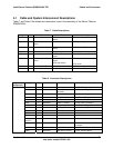
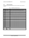
Table 7. Cable Descriptions
Type Qty From To Cable Description
Signal 1 Mainboard SCSI Backplane Board
Board
100 Pin (multi-signal function)
Signal 1 SCSI Backplane Board
Board
Front Panel I/O Board 30 Pin (multi-signal function)
SCSI 2 Mainboard SCSI Backplane Board
Board
68 Pin internal SCSI
SCSI 1 Mainboard Rear panel 68 Pin VHDCI SCSI (optional)
SATA 1 Mainboard SATA-to-IDE converter
board
7 Pin SATA
DC Power 1 SCSI Backplane Board
Board
SATA-to-IDE Converter
Board
SCSI tape device
4 Pin power (mini connector)
4 Pin power
Signal 1 Front Panel I/O Board Front panel 50 Pin (multi-signal function)
Switch 1 Mainboard Chassis intrusion switch 3 Pin switch
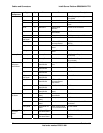
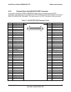
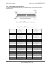
Table 8. Connector Descriptions
System
Component
Type Qty From To Interconnect Description
Processors 4 Mainboard Processor 604 Pin ZIF sockets
PCI Express* 4 Mainboard Memory Board
connector
164 Pin Card Edge Connectors
Memory 1 Mainboard ROMB DIMM 240 Pin Card Edge Connector
PCI Express 1 Mainboard Fibre Channel Module 164 Pin Card Edge Connector
VRM 1 Mainboard VRM9.1 module 62 Pin Card Edge Connector
VRM 2 Mainboard VRM10.2 module 54 Pin power connectors
PCI-X* 3 Mainboard PCI-X adapters 188 Pin Card Edge Connectors
PCI Express 4 Mainboard PCI Express adapters 98 Pin Card Edge Connectors
IMM 1 Mainboard IMM 120 Pin connector
ICMB 1 Mainboard Internal interface 1 x 5 Header connector
IPMB 1 Mainboard Internal interface 1 x 3 Header connector
Chassis
Intrusion
1 Mainboard Top cover switch 1 x 3 Header connector
USB 1 Mainboard Rear panel 1 x 4 Pin double stacked USB
connector
USB 1 Mainboard Internal interface 1 x 4 Pin connector
Mainboard
Video 1 Mainboard Rear panel, monitor 15 Pin, monitor device