


Server System Chassis and Assemblies Intel® Server Platform SR6850HW4 TPS
Revision 1.0
Intel order number D23151-001
26
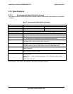
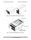
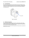
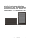
3.3 Fan Subsystem
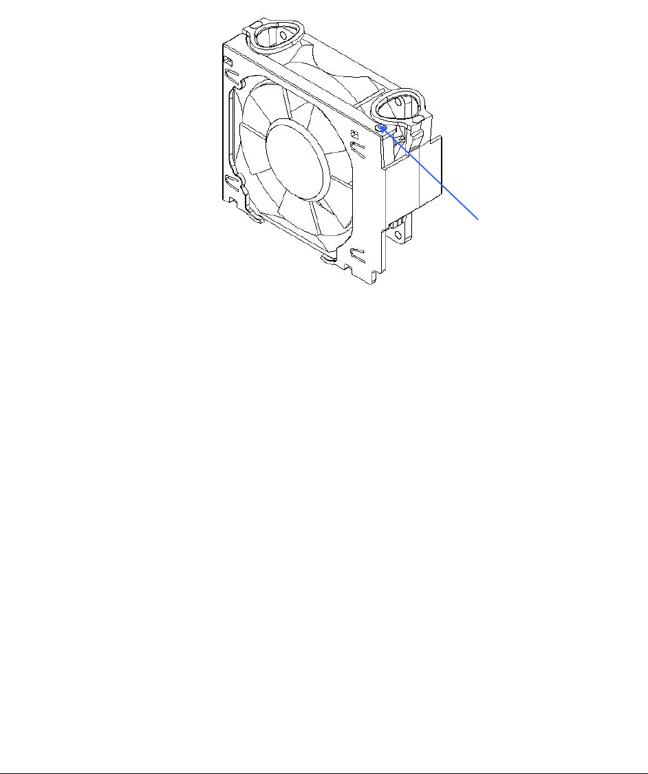
The six system fans are accessible for hot-swap operations at the top of the chassis. The fan
assembly has an integrated amber LED wired to the top of the assembly. This LED lights when
the fan is not functioning within specification. The fan connector extends from the bottom of the
fan assembly and mates into floating connectors routed to the Server Platform SR6850HW4
SCSI Backplane Board.
Figure 9. System Fan
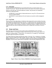
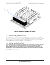
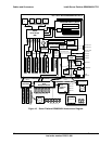
3.4 Mainboard Assembly
The Server Board Set SE8500HW4 Mainboard mounts to a sheet metal tray with four metal
springs from the Intel Component Enabling Kit (CEK) and four non-captive screws. The Server
Board Set SE8500HW4 Mainboard assembly is mounted in the chassis with slot and tab hooks.
It is secured into the chassis by a single captive fastener.
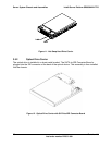
Memory Boards mount vertically on the left and right side of the board however, processors and
heatsinks mount in the front.
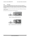
Failure LED