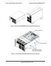
Intel® Server Platform SR6850HW4 TPS System Overview
Revision 1.0
Intel order number D23151-001
17
2.6.2 Rolling BIOS
The Server Board Set SE8500HW4 Mainboard supports two BIOS images to be stored in
Flash. This provides a mechanism for BIOS updates without a system reboot as well as
failover to an alternate image in the event of BIOS corruption. The system runs with the
current BIOS until a reboot, after which time the updated BIOS is used. See the Intel Server
Board Set SE8500HW4 Technical Product Specification for more details on this feature.
2.7 Server Management
The management subsystem conforms to the IPMI v2.0 Specification. The server
management features are implemented using two microcontrollers: the Intel Management
Module that plugs into the Server Board Set
SE8500HW4 Mainboard, and the SCSI hot-swap
controller on the SCSI Backplane Board. The functions of each component are summarized
in the following sections.
2.7.1 Intel Management Module (IMM)
The IMM has a Baseboard Management Controller (BMC) microcontroller and associated
circuitry. The IMM contains flash memory that holds the operation code and the BMC
configuration settings. The IMM monitors platform management events and logs their
occurrence on the onboard non-volatile System Event Log (SEL). This includes events such
as over-temperature and over-voltage conditions, fan failures, etc. The IMM also provides
the interface to this monitored information so system management software can poll and
retrieve the present status of the platform.
The IMM also provides the interface to the non-volatile Sensor Data Record (SDR)
repository. SDRs provide a set of information that system management software can use to
automatically configure itself for the number and type of IPMI sensors (e.g., temperature
sensors, voltage sensors, etc.) in the system.
The following is a list of the major functions for the IMM:
System power control
- ACPI power control
- ACPI sleep support
- Minimum power off time
System reset control
System initialization
- Processor temperature and voltage threshold setting
- Fault Resilient Booting (FRB)
Front panel user interface
- System status (green) LED control
- System status (amber) LED control
- System ID LED control
- Reset button control
- Power button control
- SDINT button control


