


Intel® Server Platform SR6850HW4 TPS System Overview
Revision 1.0
Intel order number D23151-001
5
TP01504
2
1
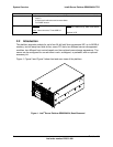
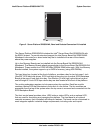
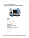
Figure 2. Server Platform SR6850HW4, Bezel and Pedestal Conversion Kit Installed
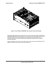
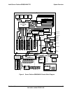
The Server Platform SR6850HW4 includes the Intel
®
Server Board Set SE8500HW4 with
the E8500 chipset. To provide structural support the Intel Server Board Set SE8500HW4
Mainboard is mounted on a sheet metal tray that is installed at the rear of the chassis,
above the power supplies.
Up to four Memory Boards can be installed into the Server Board Set SE8500HW4
Mainboard. The Memory Boards attach perpendicular to the Server Board Set SE8500HW4
Mainboard. These contain four DDR2 400HMz SDRAM DIMM slots each. With four Memory
Boards installed, the system supports up to 64GB of memory (using 4GB DIMMs).
The hard drive bay, located at the front of platform, provides a bay for ten hot-swap 1-inch
Ultra320* SCSI hard disk drives. SCSI hard disk drives plug into a vertical SCSI Backplane
Board at the rear of hard disk drive bay. One Slimline (½-inch high) optical drive bay and
one full-height 5¼-inch SCSI tape device bay are also located at the front of the platform.
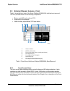
The cooling subsystem requires six hot-swap system fan modules. Each fan module
contains a status LED that illuminates in the event of a fan failure. The fan modules are
accessible from the top of the system when the top cover is removed and connected into the
SCSI Backplane Board.
The front control panel provides video, USB, buttons, status LEDs, and an optional LCD,
that are used for monitoring and managing the platform. The front bezel is an optional
cosmetic accessory that is installed with snap-on features. The bezel can be customized to
meet integrator-specific industrial design requirements, including color and imprint.