Intel® Server Platform SR6850HW4 TPS Front Panel I/O and Control Boards
Revision 1.0
Intel order number D23151-001
85
8. Front Panel I/O and Control Boards
This chapter describes the Server Platform SR6850HW4 Front Panel I/O Board and is
organized as follows:
Section 8.1: Introduction
Provides an overview of the Server Platform SR6850HW4 Front Panel
I/O Board, showing functional blocks and board layout.
Section 8.2: Functional Architecture
Describes the Server Platform SR6850HW4 Front Panel I/O Board
functional blocks.
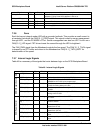
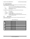
Section 8.3: Signal Descriptions
Summary of the internal and connector signals, and the connector signal
pin names and descriptions. Signal mnemonics appear throughout this
chapter.
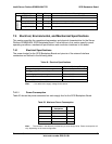
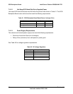
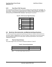
Section 8.4: Electrical, Environmental and Mechanical Specifications
Specifies operational parameters and considerations, and connector
pinouts.
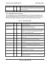
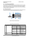
Section 8.5: Front Panel Control Module
Describes the two different front panel control modules available in the
Server Platform SR6850HW4.
8.1 Introduction
The Server Platform SR6850HW4 Front Panel I/O Board provides access to the video and USB
interfaces. It also interfaces to the front panel control module that contains the front control
panel buttons, LEDs and optional LCD window. Circuitry on the Server Platform SR6850HW4
Front Panel I/O Board consists of video filters, USB filters, USB port power bulk capacitors with
fusing, and a speaker.
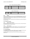
8.1.1 Block Diagram
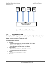
The following block diagram divides the Front Panel I/O Board into physical and functional
blocks. Arrows represent buses and signals. Blocks represent the physical and functional
circuits. Figure 32 illustrates the general architecture of the front panel.


