


Intel® Server Platform SR6850HW4 TPS Front Panel I/O and Control Boards
Revision 1.0
Intel order number D23151-001
95
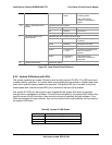
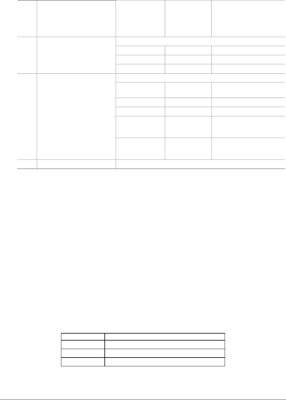
Amber, blinking Non-Critical
Alarm
Redundant power supply
or blower failure.
Non-critical blower,
voltage, or temperature
failure.
Indicates LAN activity status
Off Idle
On Inactive No access
J, K LAN1, LAN2 Status LEDs
(green)
Blinking Active Access
Indicates hard drive activity and fault status.
Green On A hard drive is being
initialized
Green Blinking A hard drive is active
Amber On Hard drive/slot failure
Amber Slow blinking
(~1 Hz)
A predictive hard drive/slot
failure or rebuild in
process
L Hard Drive Status LED
(green/amber)
Amber Fast blinking
(~2.5 Hz)
Hard drive rebuild
interrupted or rebuild on
empty slot
M System Reset button Resets the system
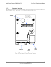
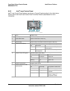
Figure 36. Local Control Panel Features
8.5.3 System ID Buttons and LEDs
The system contains two system ID buttons and two blue system ID LEDs. The LEDs are used
to easily identify a platform. It is useful when several platforms are racked or installed near each
other and a specific system needs to be serviced. One button/LED pair is located on the front
control panel and a second button/LED pair is located at the rear of the platform.
The system ID LEDs can be turned on and off either by the system ID buttons or remotely
through server management software. If the LEDs are activated by the system LED button, they
must be turned off with the button; they cannot be turned off remotely through software. If the
LEDs are activated through software, they must be turned off through software, not by pressing
the system LED button.
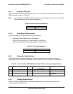
Table 60. System ID LED Details
LED State Description
Off System ID inactive.
On System ID active via button.
Blinking System ID active via remote command.