


Intel® Server Platform SR6850HW4 TPS SCSI Backplane Board
Revision 1.0
Intel order number D23151-001
79
7.3.1 Power from the Power Distribution Board
The SCSI Backplane Board receives only +12V from the Power Distribution Board through a 12-
pin connector. These pins are tied together and Table 43 provides a summary of the power
connector pins.
Table 43. Power Interface Signals
Signal Type Driver Name and Description
+12V I PWR +12 Volt supply from Power Distribution Board
7.3.2 Front Panel Power Connector
Table 44 is a summary of the Server Platform SR6850HW4 Front Panel I/O Board power
connector pins.
Table 44. Front Panel I/O Board Power Interface Signals
Signal Type Driver Name and Description
+3.3V
stby
I PWR +3.3 Volt standby supply from Front Panel I/O Board
+3.3V O PWR +3.3 Volt supply to Front Panel I/O Board
+5V O PWR +5 Volt supply to Front Panel I/O Board
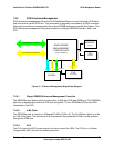
7.3.3 Front Panel I/O Board Ribbon Cable Connector
The 30-pin Server Platform SR6850HW4 Front Panel I/O Board ribbon cable connector carries
signals to and from the SCSI Backplane Board. Table 45 provides a description of the Front
Panel I/O Board ribbon cable connector. See Chapter 4 for pinouts.
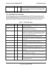
Table 45. Front Panel I/O Board Ribbon Connector Signal Description
Signal Typ
e
Driver Name and Description
FP_ID_BTN_N I Switch ID button, ground when pressed
FP_PWR_BTN_N I Switch Power button, ground when pressed
FP_RST_BTN_N I Switch Reset button, ground when pressed
SYS_STATUS_GRN_
LED_R_N
O Drives the front control panel system status green LED under
Mainboard control
SYS_STATUS_AMB_
LED_R_N
O Drives the front control panel system status amber LED under
Mainboard control
FP_ID_LED_R_N O Drives the front control panel ID blue LED under Mainboard
control
FP_PWR_LED_R_N O Drives the front control panel power green LED under Mainboard
control