


System Overview Intel® Server Platform SR6850HW4 TPS
Revision 1.0
Intel order number D23151-001
8
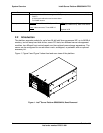
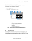
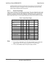
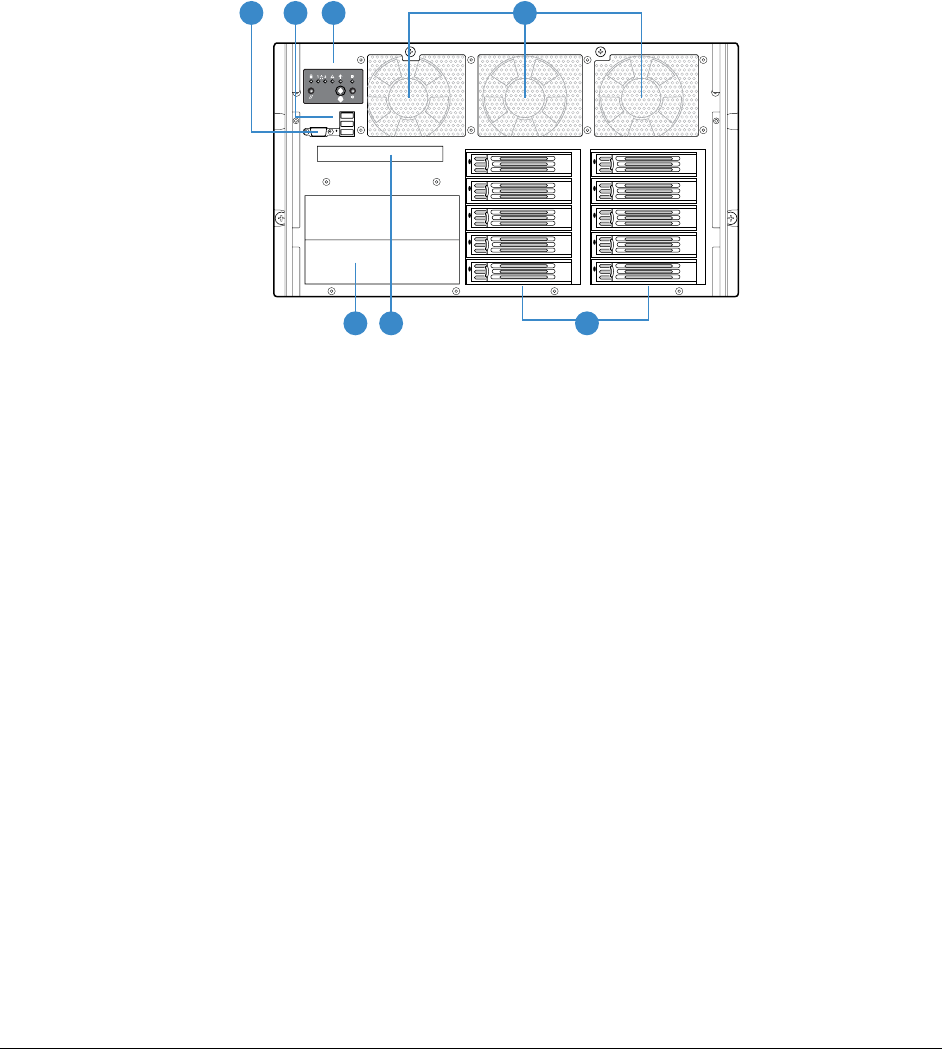
2.3 External Chassis Features - Front
Table 2 shows the front view of the Server Platform SR6850HW4 with the bezel removed.
The front provides access to the following components:
Buttons and LEDs (with optional LCD)
Video and USB connectors
Hard drive bay, optical drive, SCSI tape device
TP01508
C
A
B
E
F
D
G
A Video connector
B USB 2.0 ports (three)
C Front control panel (button control panel shown)
D Hot-swap fans (six)
E 5 ¼ peripheral bay (full height)
F Optical drive bay
G Hot-swap SCSI hard disk drives (ten)
Table 2. Front View of the Server Platform SR6850HW4, Bezel Removed
2.3.1 Front Control Panel
The front control panel contains system control buttons and LED status indicators. It also
contains one video connector, three USB 2.0 ports, NMI button, and the system speaker.
The front bezel must be removed to access the front control panel switches and connectors.
All LEDs are visible with the front bezel installed. See Chapter 8 or a description of the Front
Panel Boards.