


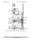

SCSI Backplane Board Intel® Server Platform SR6850HW4 TPS
Revision 1.0
Intel order number D23151-001
80
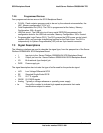
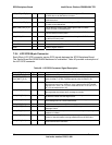
HDD_LED_ACT_R_N O Drives the front control panel drive active green LED when either
a SCSI drive or an SATA drive is active
HDD_LED_FLT_R_N O Drives the front control panel drive fault amber LED to indicate a
SCSI drive fault
NIC1_LINK_LED_R_N O Drives the front control panel LAN1 green LED to indicate status
of LAN1 on the Mainboard
NIC2_LINK_LED_R_N O Drives the front control panel LAN22 green LED to indicate
status of LAN2 on the Mainboard
I2C_IPMB_SCL I/O This pin supplies an isolated version of the global IPMB Bus
clock to the front control panel.
I2C_IPMB_SDA I/O This pin supplies an isolated version of the global IPMB Bus data
to the front control panel.
+5V O Power for the front control panel
+5V STBY O Power for the blue LED on the front control panel
GND O Ground, signal common
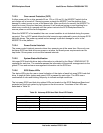
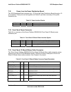
7.3.4 LVD SCSI 68-pin Connector
Each 68-pin LVD SCSI connector carries SCSI signals between the SCSI Backplane Board.
The Server Board Set SE8500HW4 Mainboard is unshielded. Table 46 provides a description of
the LVD SCSI connector.
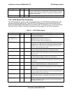
Table 46. LVD SCSI Connector Signal Description
Signal Type Driver Name and Description
LVD_DB[15..0]_[P, N] I/O LVD hs SCSI data bus. The data bits for the differential SCSI bus.
LVD_DBP_[P, N]
LVD_DBP1_[P, N]
I/O LVD hs SCSI data parity. Support parity on the SCSI bus. DB_P0[P/N] supports
parity for data [7..0]. DB_P1[P/N] supports parity for data [15..8].
DIFFSENSE I Analog Differential sense. The voltage level determines the operating mode of
the target devices on the SCSI bus. If the voltage on the DIFFSENSE
signal is from –0.35 V to +0.5 V the mode will be SE. If it is from +0.7 V
to 1.9 V the mode will be LVD.
LVD_ATN_[P, N] I/O LVD hs SCSI bus attention. Asserted by a SCSI device in initiator mode to alert
the target that the initiator has a message to transfer.
LVD_BSY_[P, N] I/O LVD hs SCSI bus busy. Indicate that the SCSI bus is being used. Can be driven
by both the initiator and the target device.
LVD_ACK_[P, N] I/O LVD hs SCSI bus acknowledge. Driven by an initiator, indicating an
acknowledgement for a SCSI data transfer.
LVD_RST_[P, N] I/O LVD hs SCSI bus reset. Indicate a SCSI bus reset condition.
LVD_MSG_[P, N] I/O LVD hs SCSI bus message phase. Driven by a SCSI target to indicate it is in the
Message Phase.
LVD_SEL_[P, N] I/O LVD hs SCSI bus select. Used by an initiator to select a target or by a target to
reselect an initiator.
LVD_CD_[P, N] I/O LVD hs SCSI bus control/data phase. Driven by a target, these pins indicate that
control or data information is being transferred over the SCSI bus.
LVD_REQ_[P, N] I/O LVD hs SCSI bus request. Driven by a target, these pins indicate a request for a
SCSI data-transfer handshake.