


Cables and Connectors Intel® Server Platform SR6850HW4 TPS
Revision 1.0
Intel order number D23151-001
42
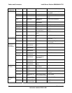
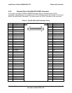
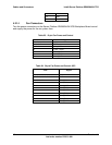
16 LVD_RST_N 36 +5V 56 LVD_RST_P 76 GND
17 LVD_ACK_N 37 NC 57 LVD_ACK_P 77 SCSI_ACT
18 LVD_BSY_N 38 GND 58 LVD_BSY_P 78 NC
19 LVD_ATN_N 39 SCSI_ID (0) 59 LVD_ATN_P 79 SCSI_ID(1)
20 LVD_DBP_N 40 SCSI_ID (2) 60 LVD_DBP_P 80 SCSI_ID(3)
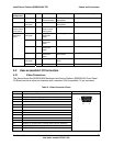
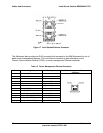
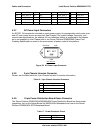
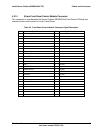
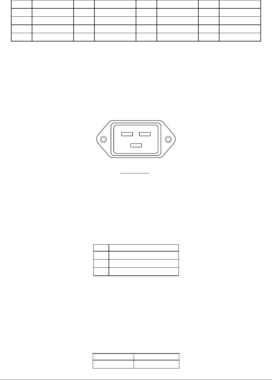
4.2.7 AC Power Input Connectors
An IEC320 15A receptacle is located on each power supply. An appropriately sized power cord
and AC main power source are required. See Chapter 5 for system voltage, frequency, and
current draw specifications. An external AC cord retention feature is supported by the chassis
but is not supplied by Intel. Please refer to the Server Platform SR6850HW4 Power Cord
Enabling Specification to assist in the procurement of power cords for the platform.
NEUTRAL LINE
GND
IEC 320 C19
Figure 20. AC Power Input Connector
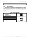
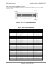
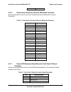
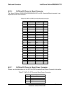
4.2.8 3-pin Chassis Intrusion Connector
Please, see the table below for 3-pin Chassis Intrusion Connector information.
Table 16. 3-pin Chassis Intrusion Connector
Pin Signal
1 Intrusion event
2 GND
3 Intrusion button attached
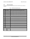
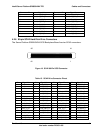
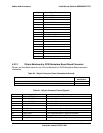
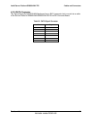
4.2.9 12-pin Power Distribution Board Power Connector
The Server Platform SR4850HW4/SR6850HW4 Power Distribution Board has three power
connectors, two for the Server Board Set SE8500HW4 Mainboard and one for the Server
Platform SR6850HW4 SCSI Backplane Board.
Table 17. Power Connector Pinout
Pins Signal
1-6 GND