


Cables and Connectors Intel® Server Platform SR6850HW4 TPS
Revision 1.0
Intel order number D23151-001
44
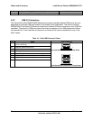
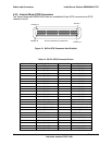
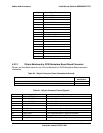
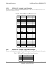
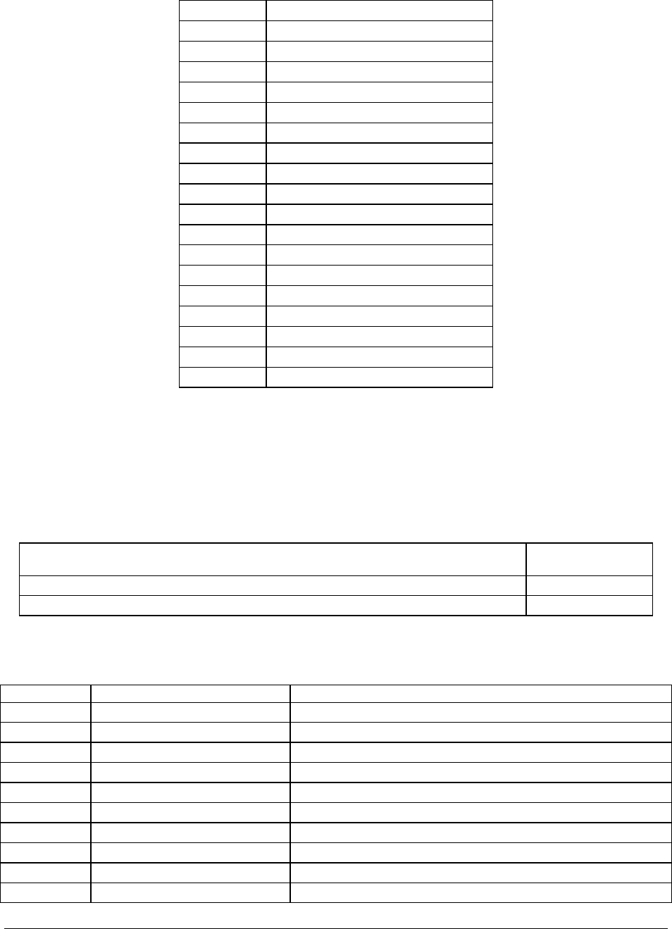
Pins Signal Description
5 USB Hub DPD2
6 USB Hub DMD2
8 USB Hub DPD3
9 USB Hub DMD3
11 USB1 overcurrent output, active high
12 USB2 overcurrent
13 USB3 overcurrent
14 NMI button, active low
15 Video DCC out SCLCK
16 Video DCC out SDA
17 Video vertical sync
18 Video horizontal sync
20 Video red
22 Video green
24 Video blue
27 Speaker drive, active high
29 Monitor presence, active low
30 Unused, keying pin
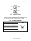
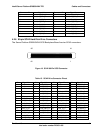
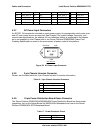
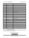
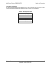
4.2.12 100-pin Mainboard to SCSI Backplane Board Board Connector
Please, see the tables below for the 100-pin Mainboard to SCSI Backplane Board connector
information.
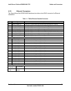
Table 20. 100-pin Connector Pinout (Unused and Ground)
Pin Numbers Signal
Descriptions
1,3,7,10,14,20,27,42,51,52,54,58,62,65,73,77,79,82,83,85,87,89,91,93,95,100 Ground
4,6,8,12,13,15,17,19,22,24,26,29,31,33,35,37,41,44,46,48,50,53,56,59,61,66,68,70,72 Unused
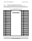
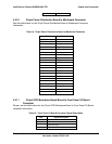
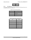
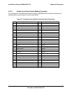
Table 21. 100-pin Connector Pinout (Signals)
Pin Number Signal Name Signal Description
2 GND – RESISTOR Ground through zero ohm resistor
5 GND – RESISTOR Ground through zero ohm resistor
9 GND – RESISTOR Ground through zero ohm resistor
11 GND – RESISTOR Ground through zero ohm resistor
16 FAN1_TACH Fan 1 Tachometer signal – edges per revolution
18 FAN2_TACH Fan 2 Tachometer signal – edges per revolution
21 FAN3_TACH Fan 3 Tachometer signal – edges per revolution
23 FAN4_TACH Fan 4 Tachometer signal – edges per revolution
25 RESET_BTN Front panel reset button signal
28 FAN5_TACH Fan 5 Tachometer signal – edges per revolution