


Cables and Connectors Intel® Server Platform SR6850HW4 TPS
Revision 1.0
Intel order number D23151-001
36
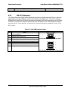
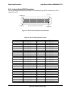
Pin Signal Name and Description Video Connector
15 MONID2 (to support DDCx, Display Data Channel standard)
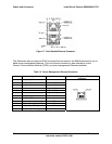
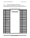
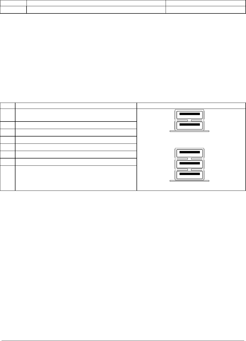
4.2.2 USB 2.0 Connectors
The Server Board Set SE8500HW4 Mainboard provides a double-stacked USB port at the rear
panel and one vertical USB port located in the middle of the Mainboard. The Server Platform
SR6850HW4 Front Panel I/O Board provides three stacked USB port connectors via a USB hub
controller. These built-in USB ports permit the direct connection of six USB peripherals without
an external hub. If more devices are required, an external hub can be connected to any of the
built-in ports.
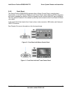
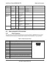
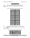
Table 10. Dual USB Connector Pinout
Pin Signal USB Connectors
A1 Fused Voltage Controlled Current (VCC) (+5 V with over-
current monitoring)
A2 USBPxM (differential data line)
A3 USBPxP (differential data line)
A4 GND (ground)
B1 Fused VCC (+5 V with over-current monitoring)
B2 USBPxM (differential data line)
B3 USBPxP (differential data line)
B4 GND (ground)
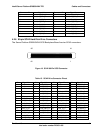
1
2
Dual Stacked USB Connector on Rear Panel
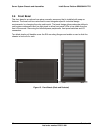
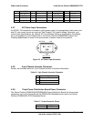
1
2
3
Triple Stacked USB Connector on Front Panel