


Intel® Server Platform SR6850HW4 TPS Cables and Connectors
Revision 1.0
Intel order number D23151-001
35
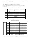
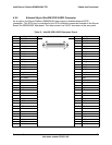
System
Component
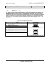
Type Qty From To Interconnect Description
DC power 1 SATA-to-IDE
Converter Board
SCSI Backplane
Board Board
1 x 4 Pin header (mini connector)
Fan module DC power
and signal
6 Fan SCSI Backplane
Board Board
2 x 6 Pin header
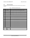
Button control
panel or Local
control panel
Signal 1 Button control
panel or Local
control panel
Front Panel I/O Board 50 Pin header
DC power
and signal
2 Power
Distribution
Board
Power supply 34-blade connector
DC power 2 Power
Distribution
Board
Mainboard 1 x 12 Pin connector
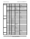
Signal 1 Power
Distribution
Board
Mainboard 2 x 15 Pin header
Power
Distribution
Board
DC power 1 Power
Distribution
Board
SCSI Backplane
Board Board
1 x 12 Pin connector
DC power
and signal
1 Power supply Power Distribution
Board
34-blade connector Power Supply
AC power 1 Power supply External interface IEC filtered 15A receptacle
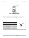
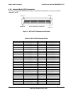
4.2 User-accessible I/O Connectors
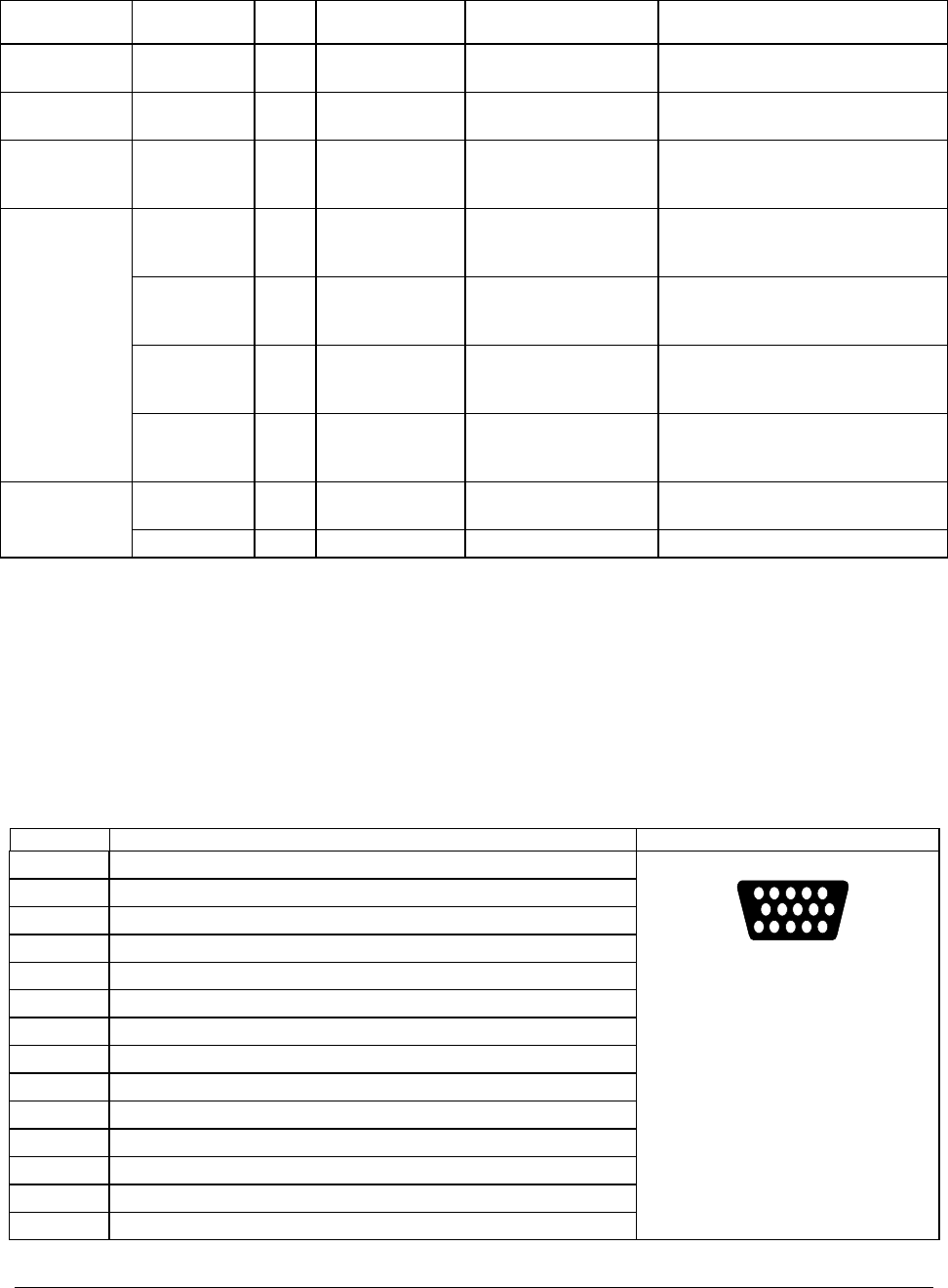
4.2.1 Video Connectors
The Server Board Set SE8500HW4 Mainboard and Server Platform SR6850HW4 Front Panel
I/O Board provide a video port interface with a standard VGA-compatible, 15-pin connector.
Table 9. Video Connector Pinout
Pin Signal Name and Description Video Connector
1 VID_R (analog color signal red)
2 VID_G (analog color signal green)
3 VID_B (analog color signal blue)
4 No connection
5 GND
6 GND
7 GND
8 GND
9 No connection
10 GND
11 No connection
12 MONID1 (to support DDCx, Display Data Channel* standard)
13 VID_HSYNC (horizontal sync)
14 VID_VSYNC (vertical sync)
5 1
15 11
610