


Intel® Server Platform SR6850HW4 TPS SCSI Backplane Board
Revision 1.0
Intel order number D23151-001
67
7. SCSI Backplane Board
This chapter describes the Server Platform SR6850HW4 SCSI Backplane Board and is
organized as follows:
Section 1: Introduction
Provides an overview of the Server Platform SR6850HW4 SCSI
Backplane Board, showing functional blocks and the board layout.
Section 2: Functional Architecture
Describes the Server Platform SR6850HW4 SCSI Backplane Board
functional blocks.
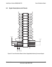
Section 3: Signal Descriptions
Summary of the Server Platform SR6850HW4 SCSI Backplane Board
internal signals and connector signals, and the connector signal pin
names and the signal descriptions.
Section 4: Electrical, Environmental, and Mechanical Specifications
Specifies operational parameters and considerations, and connector
pinouts.
7.1 Introduction
The Server Platform SR6850HW4 SCSI Backplane Board supports up to ten hot-swap Ultra320
SCSI hard disk drives mounted into the chassis. The board provides drive status information
and allows adding, removing and replacing hard disk drives without powering down the system.
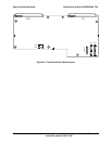
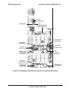
The following block diagram, architectural overview, and placement diagram provide an
overview of the Server Platform SR6850HW4 SCSI Backplane Board.
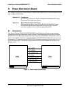
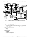
7.1.1 Block Diagram
The block diagram divides SCSI Backplane Board into physical and functional blocks. Arrows
represent buses and signals. Blocks represent the physical and functional blocks.