


Intel® Server Platform SR6850HW4 TPS Cables and Connectors
Revision 1.0
Intel order number D23151-001
45
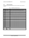
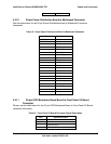
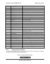
Pin Number Signal Name Signal Description
30 FAN6_TACH Fan 6 Tachometer signal – edges per revolution
32 FAN_PWM1 Zone 1 Fan PWM control signal
34 5VSTANDBY 5V standby to front panel
36 BP_D2D_EN Backplane D2D enable
38 5VSTANDBY 5Vstandby to front panel
39 ICH5_PDD8 IDE primary disk data 8
40 HD_ACT_N SATA Hard Drive Activity
43 BP_PWRGOOD Backplane power good signal
45 PCI_RST_BP_N PCI reset to backplane
47 CP_PWR_LED Control Panel Power LED signal
49 CP_SPKR_OUT_N Speaker signal to front panel
55 NIC1_LED NIC 1 activity LED signal
57 ID_LED ID LED Signal
60 CP_BTN_PWR_ON Control panel Power Button signal
63 SYS_STATUS_AMB_LED System Status amber LED signal
64 CD_PRES_N CD drive presence signal
67 CP_ID_BUTTON_RAW Control panel ID button signal
69 CP_BTN_NMI Control panel NMI button
71 NIC2_LED NIC2 activity LED signal
74 I2C_IPMB_SCL IPMB I
2
C bus clock
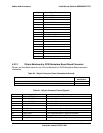
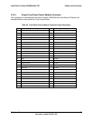
75 BP_PRES_N SCSI Backplane Board Board presence signal, indicates System
Board interlock is achieved
76 I2C_IPMB_SDA IPMB I
2
C bus data
78 SYS_PWRGD4 Mainboard power good signal to SCSI Backplane Board Board
80 USB_FRONT_N USB port 2 differential negative signal to front bezel
81 USB_FRONT_P USB port 2 differential positive signal to front bezel
84 VID_RED_FRONT Video DAC 2 RED signal
86 VID_BLUE_FRONT Video DAC 2 BLUE signal
88 VID_GREEN_FRONT Video DAC 2 GREEN signal
90 VID_HS_OUT_FRONT Video DAC 2 Horizontal Synchronization signal
92 VID_VS_OUT_FRONT Video DAC 2 Vertical synchronization signal
94 VID_DDC_OUT_SCLK_FRONT Video Monitor detection I
2
C bus clock
96 VID_DDC_OUT_SDA_FRONT Video monitor detection I
2
C bus data
97 I2C_CP_SDA Control panel I
2
C bus data (I
2
C segment 2)
98 SYS_STATUS_GRN_LED System status green LED signal
99 I2C_CP_SCL Control panel I
2
C bus data (I
2
C segment 2)
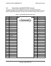
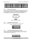
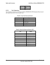
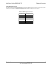
4.2.13 Peripheral Power Connector
The Server Platform SR6850HW4 SCSI Backplane Board provides a standard power connector
to drive both the SCSI tape device and optical drive.
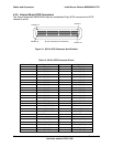
Table 22. Peripheral Power Connector
Pins Signal