


Intel® Server Platform SR6850HW4 TPS SCSI Backplane Board
Revision 1.0
Intel order number D23151-001
77
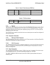
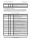
Table 41. Global I
2
C Bus Addresses (IPMB Bus)
Device Address Bus/Location Description
Bus A GEM359 0xC0 Legacy I
2
C/SCSI Backplane Board
Board
Microcontroller public IPMB bus
Bus B GEM359 0xC2 Legacy I
2
C/SCSI Backplane Board
Board
Microcontroller public IPMB bus
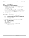
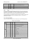
Table 42. I
2
C IO Bus Address
Device Address Bus/Location Description
PCA9555 0x42 Legacy I
2
C/SCSI Backplane Board
Board
Microcontroller public I/O bus
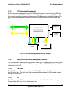
7.2.5 Resets
The PCI_RST_BP_N signal from the Server Board Set SE8500HW4 Mainboard via the 100-pin
connector provides the principal reset for the logic on the SCSI Backplane Board. The signal
resets the USB hub and SCSI drive power sequencing timing in the PLD. The PLD resets the
GEM359s and their flash chips.
The PCA9555 device used to control the fans has an internal power-on reset that configures all
its I/O pins as inputs.
7.2.6 Connector Interlocks
7.2.6.1 Mainboard Cable Connector
The SCSI Backplane Board has an interlock on the 100-pin connector so the Server Board Set
SE8500HW4 Mainboard can detect its presence.
7.2.6.2 SCA-2 Connector
The SCSI Backplane Board uses an interlock to determine if a hot-swap SCSI hard disk drive is
present. This interlock is defined by the SCSI_MATED# signals. Drive presence is used by
enclosure management.
7.2.7 Clock Generation
The SCSI Backplane Board has a single, 10.0MHz, local clock. It supplies a 5V-rail clock input
to the GEM359s and PLD. The clock is separately buffered by a 74LVT244.
The SMSC* USB20H04 USB hub has its own built-in 24MHz crystal oscillator that uses an
external crystal.