


Intel® Server Platform SR6850HW4 TPS Front Panel I/O and Control Boards
Revision 1.0
Intel order number D23151-001
89
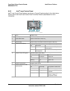
8.3 Signal Descriptions
The following notations are used to describe the signal type, from the perspective of the Server
Platform SR6850HW4 Front Panel I/O Board:
I Input pin to the Server Platform SR6850HW4 Front Panel I/O Board
O Output pin from the Server Platform SR6850HW4 Front Panel I/O Board
I/O Bi-directional (input/output) pin
PWR Power supply pin
The signal description also includes the type of buffer used for the particular signal:
TTL 5V TTL signals
CMOS 5V CMOS signals
3.3V CMOS 3.3V CMOS signals
Analog Typically a voltage reference or specialty power supply
hs This suffix is added to indicate high-speed requirements that would make
modifications subject to review
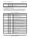
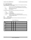
8.3.1 USB Connector
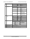
Table 53 provides a summary of power connector pins, including the signal mnemonic, the
name, and a brief description.
Table 53. USB Connector
Signal Type Driver Name and Description
USB_FB_OC1 Connector, TOP
USB_P1_CONN_M I/O
USB_P1_CONN_P I/O
USB port
1(J6K1)
USB_P1_CABLE_GND
USB_FB_OC2 Connector, CENTER
USB_P2_CONN_M I/O
USB_P2_CONN_P I/O
USB port
2(J5K1)
USB_P2_CABLE_GND
USB_FB_OC3 Connector, BOTTOM
USB_P3_CONN_M I/O
USB_P3_CONN_P I/O
USB port
3(J6K1)
USB_P3_CABLE_GND