


SCSI Backplane Board Intel® Server Platform SR6850HW4 TPS
Revision 1.0
Intel order number D23151-001
78
7.2.8 Programmed Devices
Four programmed devices are on the SCSI Backplane Board:
FLASH: Flash contains program code to be run by the onboard microcontroller, the
HSC. Memory configuration: 512 K x 8.
Field Replaceable Unit (FRU): The FRU is programmed at the factory. Memory
Configuration: 256 x 8 serial.
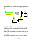
USB hub circuit: The USB hub circuit has a serial EEPROM programmed with
configuration data for the USB hub controller. Memory Configuration: 256 x 8 serial.
Programmable Logic Device (PLD): The PLD governs the SCSI power control circuit,
controls LEDs, and provides a deglitching function for the Flash chips. The PLD is
independently In-System-Programmable (ISP) with an 8-pin header connector.
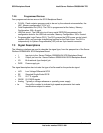
7.3 Signal Descriptions
The following notations are used to describe the signal type, from the perspective of the Server
Platform SR6850HW4 SCSI Backplane Board:
I Input pin to the Server Platform SR6850HW4 SCSI Backplane Board
O Output pin from the Server Platform SR6850HW4 SCSI Backplane Board
I/O Bi-directional (input/output) pin
PWR Power supply pin
The signal description also includes the type of buffer used for the particular signal:
LVD Low Voltage Differential SCSI
SE Standard Single Ended SCSI
TTL 5V TTL signals
CMOS 5V CMOS signals
Analog Typically a voltage reference or specialty power supply
hs This suffix is added to indicate high-speed requirements that make
modifications subject to review