


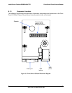
Intel® Server Platform SR6850HW4 TPS SCSI Backplane Board
Revision 1.0
Intel order number D23151-001
83
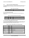
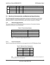
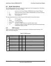
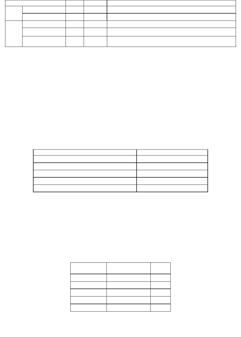
Signal Type Driver Name and Description
PWR_TIMER O Analog Power timer. Starts one second timer for FET reset.
TMR_DONE I Analog Timer done. One second reset timer complete.
FAN_PRES[1-6] I Analog Fan is present on system
FAN_LED[1-6] I Analog LED signal when fan was off line
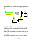
Fan Control
FAN_TACH[1-6] I Analog Fan speed
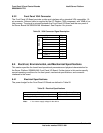
7.4 Electrical, Environmental, and Mechanical Specifications
This section specifies the operational parameters and physical characteristics for the Server
Platform SR6850HW4 SCSI Backplane Board. Further topics in this section specify normal
operating conditions, mechanical specifications and connector interfaces to the board.
7.4.1 Electrical Specifications
The power budget for the SCSI Backplane Board and pinouts of the external interface
connectors are defined in the following table.
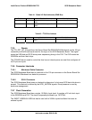
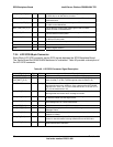
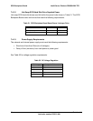
Table 49. Electrical Specifications
Feature Absolute Maximum Rating
Voltage of any signal with respect to ground -0.3V to Vcc
1
to Vcc
1
+0.3V
+3.3V
stby
supply with respect to ground -0.3V to +3.465V
+3 .3V supply with respect to ground -0.3V to +3.465V
+5V supply with respect to ground -0.3V to +5.25V
+12V supply with respect to ground -0.3V to +12.6V
Note:
1
. Vcc refers to the supply voltage for the device.
7.4.1.1 Power Consumption
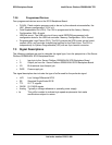
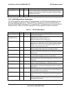
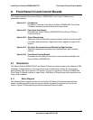
Table 50 shows the power consumed on each supply line for the SCSI Backplane Board.
Table 50. Maximum Power Consumption
Devices Power
Dissipation
Ext/Int
12V 180W Ext
5V 100W Int
3.3V 0.5W Int
3.3V
stby
0.5W Ext
1.8V 0.2W Int
Note: The numbers in the table are provided only to show design limits. Power consumption will
vary, depending on the exact configuration.