


Before you begin, print all the related instructions or ensure that you can view the PDF version on another
computer for reference.
Notes:
• If you remove the TR 700 Battery, you will lose the backup power for the ThinkServer RAID 700 Adapter.
• Use any documentation that comes with the TR 700 Battery and follow those instructions in addition to
the instructions in this topic.
To remove the TR 700 Battery, do the following:
1. Remove all media from the drives and turn off all attached devices and the server. Then, disconnect all
power cords from electrical outlets and disconnect all cables that are connected to the server.
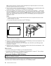
2. If the server is installed in a rack cabinet, remove the server from the rack cabinet and place it on a at,
clean, and static-protective surface. See the Rack Installation Instructions that comes with the server.
3. Remove the server cover. See “Removing the server cover” on page 69.
4. Remove the cooling shroud. See “Removing and reinstalling the cooling shroud” on page 73.
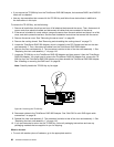
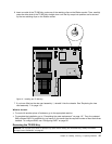
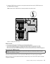
5. Locate the ThinkServer RAID 700 Adapter, which is installed in the PCI Express card slot on the riser
card assembly 2. Then, disconnect all cables from the ThinkServer RAID 700 Adapter.
6. Remove the riser card assembly 2. The procedure is similar to that of the riser card assembly 1. See
“Replacing the riser card assembly 1” on page 143.
7. Remove the ThinkServer RAID 700 Adapter from the riser card assembly 2. See “Installing or removing
the RAID card” on page 85.
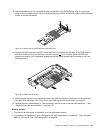
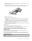
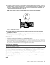
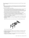
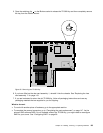
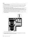
8. Remove the three screws rst. Then, hold the TR 700 Battery and lift it up from the ThinkServer RAID
700 Adapter.
Note: Center the screwdriver when you remove the screws to avoid possible damage to any parts.
Figure 50. Removing the TR 700 Battery
9. Reinstall the ThinkServer RAID 700 Adapter to the riser card assembly 2. See “Installing or removing
the RAID card” on page 85.
10. Reconnect cables to the ThinkServer RAID 700 Adapter. See “Mini-SAS to mini-SAS signal cable
connections” on page 29.
11. Reinstall the riser card assembly 2. The procedure is similar to that of the riser card assembly 1. See
“Replacing the riser card assembly 1” on page 143.
Chapter 6. Installing, removing, or replacing hardware 95