


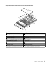

The following illustrations show the connectors on the backplane for 2.5-inch hard disk drives.
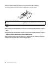
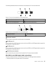
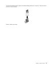
Figure 19. Front view of the backplane for 2.5-inch hard disk drives
1 Slot 0 for a 2.5-inch hard disk drive 4 Slot 5 for a 2.5-inch hard disk drive
2 Slot 2 for a 2.5-inch hard disk drive 5 Slot 3 for a 2.5-inch hard disk drive
3 Slot 4 for a 2.5-inch hard disk drive 6 Slot 1 for a 2.5-inch hard disk drive
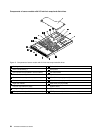
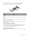
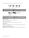
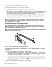
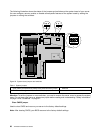
Figure 20. Rear view of the backplane for 2.5-inch hard disk drives
1 8-pin power connector
3 Mini-SAS ports 0-3
2 Mini-SAS ports 4-5 4 Optical drive power connector
1 8-pin power connector
Used to connect a power cable to provide power to the backplane.
2 Mini-SAS ports 4-5
Used to connect the mini-SAS connector on one end of a mini-SAS to mini-SAS signal cable to support the
hard disk drive 4 to hard disk drive 5.
3 Mini-SAS ports 0-3
Used to connect the mini-SAS connector on one end of a mini-SAS to mini-SAS signal cable to support the
hard disk drive 0 to hard disk drive 3.
4 Optical drive power connector
Used to connect the power cable for the slim optical drive if the server has one installed.
Mini-SAS to mini-SAS signal cable connections
This topic provides instructions on the following mini-SAS to mini-SAS signal cable connections:
• Connecting cables from the system board to the backplane
Chapter 3. Product overview 29