


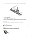
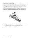
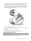
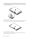


9. Position the new riser card assembly 1 on the chassis and align it with the riser card assembly 1 slot on
the system board and align the rear of it with the corresponding rail guides in the rear of the chassis.
Then, press the new riser card assembly 1 straight down until it is securely seated in the slot.
Note: If there is any PCI Express card (such as an Ethernet card) installed on the riser card assembly 1,
install the PCI Express card to the new riser card assembly 1 rst. See “Installing the Ethernet card” on
page 81
. Then, refer to your note to reconnect any cables to the PCI Express card on the new riser
card assembly 1 and properly route all the cables.
Figure 96. Installing the riser card assembly 1
10. If you are instructed to return the old riser card assembly, follow all packaging instructions and use any
packaging materials that are supplied to you for shipping.
What to do next:
• To work with another piece of hardware, go to the appropriate section.
• To complete the replacement, go to “Completing the parts replacement” on page 147.
Replacing the system board battery
Attention: Do not open your server or attempt any repair before reading and understanding “Safety information”
on page iii and “Guidelines” on page 67.
This topic provides instructions on how to replace the system board battery.
Chapter 6. Installing, removing, or replacing hardware 145