


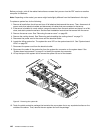


Before you begin, print all the related instructions or ensure that you can view the PDF version on another
computer for reference.
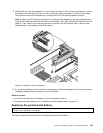
Note: Depending on the model, your server might look slightly different from the illustrations in this topic.
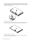
To reinstall the server cover and reconnect cables to your server, do the following:
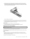
1. Ensure that all components have been reassembled correctly and that no tools or loose screws are
left inside your server.
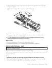
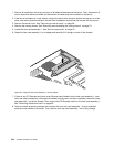
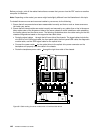
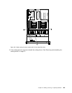
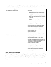
2. Ensure that all internal cables are routed correctly and secured by any cable clips or ties in the server.
Keep cables clear of the hinges and sides of the server chassis to avoid interference with reinstalling
the cooling shroud and the server cover. The following illustrations show the cable routing for the two
chassis congurations based on the supported hard disk drives.
• Route the signal cables
1 through the left inner side of the chassis. The signal cables include the
mini-SAS to mini-SAS signal cable, the front panel cable, the front panel USB cable, the diagnostic
module cable, and the SATA signal cable for the optical drive.
• Connect the power cable 2 for the optical drive to the optical drive power connector on the
backplane and properly route the cable in the chassis.
• Route the backplane power cable
3 through the right inner side of the chassis.
Figure 99. Cable routing for server models with 3.5-inch hard disk drives
148 ThinkServer RD330 User Guide