


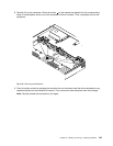
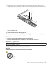
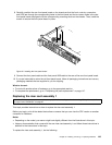
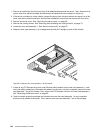
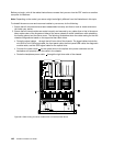
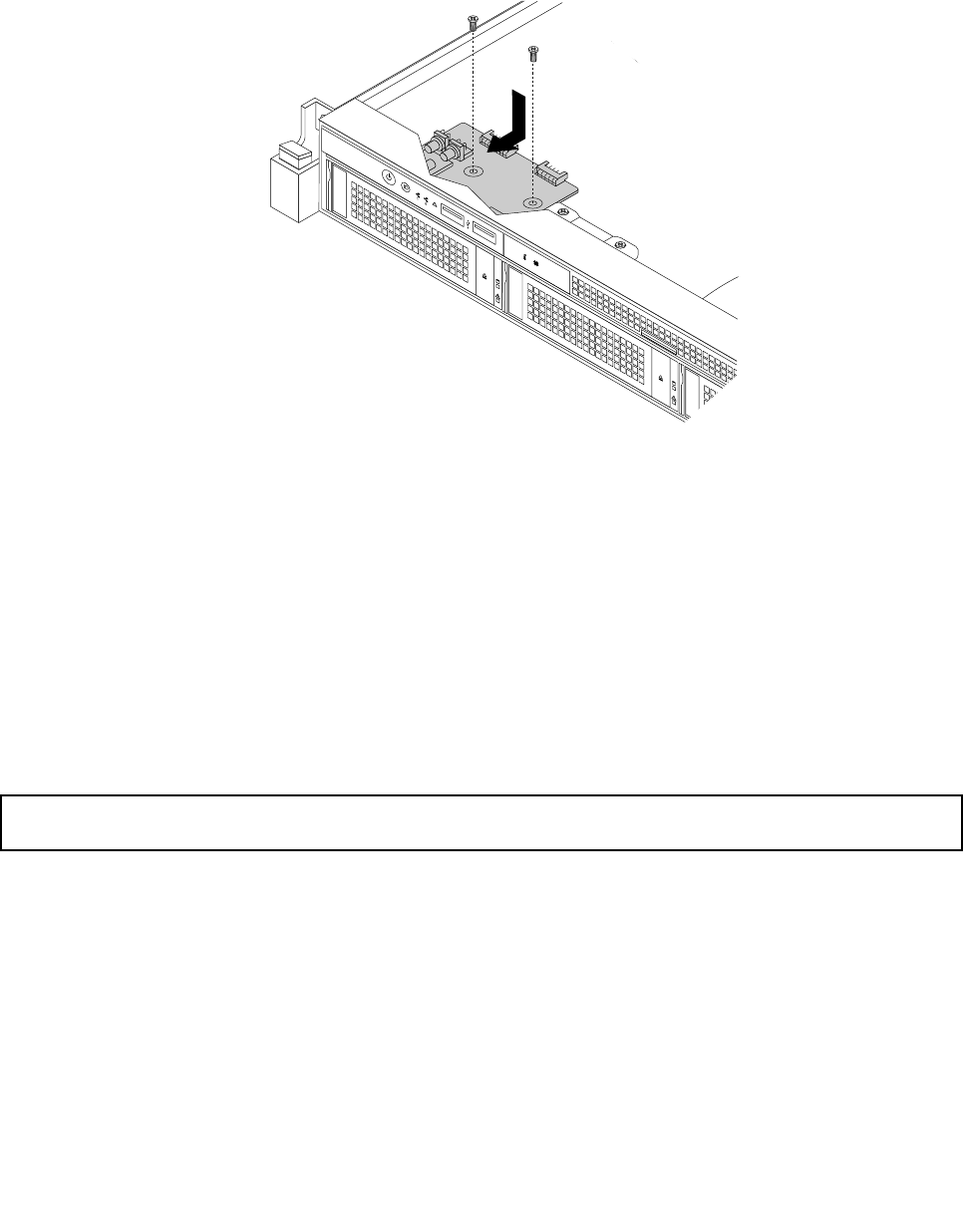
8. Carefully position the new front panel board on the chassis so that the front controls, connectors,
and LEDs are through the corresponding holes in the front bezel and the two screw holes in the new
front panel board are aligned with the corresponding mounting studs on the chassis. Then, install the
screws to secure the front panel board in place.
ID
Mem
CPU
PSU
Figure 94. Installing the front panel board
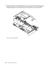
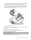
9. Connect the front panel cable and the front panel USB cable to the rear of the new front panel board.
10. If you are instructed to return the old front panel board, follow all packaging instructions and use any
packaging materials that are supplied to you for shipping.
What to do next:
• To work with another piece of hardware, go to the appropriate section.
• To complete the replacement, go to “Completing the parts replacement” on page 147
.
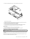
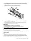
Replacing the riser card assembly 1
Attention: Do not open your server or attempt any repair before reading and understanding “Safety information”
on page iii and “Guidelines” on page 67.
This topic provides instructions on how to replace the riser card assembly 1.
Before you begin, print all the related instructions or ensure that you can view the PDF version on another
computer for reference.
Notes:
• Depending on the model, your server might look slightly different from the illustrations in this topic.
• Use any documentation that comes with the new riser card assembly 1 and follow those instructions in
addition to the instructions in this topic.
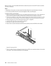
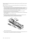
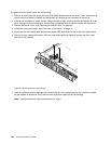
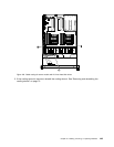
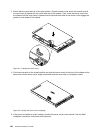
To replace the riser card assembly 1, do the following:
Chapter 6. Installing, removing, or replacing hardware 143