


Customizing Frameworks in Designer ION 7500 / ION 7600 User’s Guide
Page 112 Chapter 4 - Using ION Software
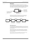
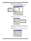
Follow the steps below to link modules on the meter:
1. Click on the symbol on the right side of the module icon to list a module’s
output registers. (To list the module’s setup registers, hold the CTRL key while
clicking on the symbol.) In most cases, a pop-up menu appears and lists
the available registers. If the module has many registers, a dialog box appears
instead.
2. Click on the register you want to select. In the case of the dialog box, double-click
on an output register, or choose the register and click Select.
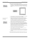
3. Drag the cursor towards the module to which you want to link; the cursor
changes and a dotted line follows it across the node diagram. This indicates you
are in the process of creating a link. The dotted line also shows where the
connecting line will appear in the node diagram once the link is made.
If you link to a module that is in a different window than the original module
(either in a different node diagram or grouping window), the dotted line
disappears, but the cursor still indicates that a link is in progress.
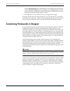
4. Click on the module icon’s left symbol to display the module’s inputs. In
most cases, a pop-up menu appears and lists the module’s inputs. (If there are a
large number of inputs, a dialog box similar to the More Output Registers dialog
box appears instead.) Inputs that are a different class than the selected output
register are grayed out to indicate that you cannot select them.
If the input is already linked, the register label it is linked to is displayed beside
the input. If you select the input, the existing link is overwritten.
5. Choose the input you want from the pop-up or dialog box.
If the two modules are in the same window, the dotted line remains on the
screen to show the link between the modules.
6. Save the changes you made to the node. When you save, the line changes from
a dotted line to a thin black line to indicate that the link is now programmed
on the node.
The procedure described above can also be performed in reverse order. You can
select a module’s input first and then link it to another module’s output register.
Accessing module outputs
or
Accessing module inputs
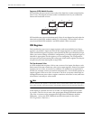
The cursor looks like this when
a linking operation is in
progress: