


ION 7500 / ION 7600 User’s Guide Displaying Data from Other Meters
Custom Front Panel Displays Technical Note Page 207
Configure the following setup registers as needed: Slave Address, Register
Address, Number of Registers read by the module, Format and scaling
requirements. The supported Slave Address range (Unit ID on ION meters) for a
Modbus device is from 1 to 247.
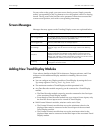
5. Repeat steps 2 - 4 for every meter or TRAN in the serial network whose data you
wish to display on the meter with the front panel.
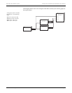
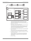
The meter with the front panel requires a separate Modbus Import module for
each meter whose data it displays, because all meters in the network have
unique Unit IDs. This is how the Modbus Master distinguishes which meter
(Slave Address) is providing what data (Register Address).
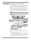
6. Link each Modbus Import module’s output registers to the appropriate Display
module’s Source inputs.
7. Define each Display module’s characteristics (display format) by adjusting its
setup registers. Do the same to the Display Options module if so desired.
8. See “Removing a Display Screen” on page 198 for considerations on re-linking
Scroll module Tri gger outputs.
This step is important if you want to have your new screens appear in an
automatic scrolling cycle, or if your custom framework has fewer display
screens than the factory configuration, and you need to adjust the Scroll
module’s settings.
9. Send & Save changes.
RS-485
Display Module 4
Source 1
Source n
Show
Display Module 3
Source n
Show
Display Module 2
Source 1
Source 2
Show
Display Module 1
Source 1
Source n
Show
Modbus Import
Module 3
Value 1
Value n
(ION 7300 TRAN)
Modbus Import
Module 2
Value 1
Value n
(ION 6200)
Value 2
Modbus Import
Module 1
Value 1
Value n
(ION 7500 TRAN)
Scroll Module
Enable
Down
Freeze
Up
Trigger 4
Trigger 3
Trigger 2
Trigger 1
Display
Options
Module
ION 7500 TRAN ION 7300 TRANION 6200
ION 7500
w/ front panel display