


Retrofit Options ION 7500 / ION 7600 User’s Guide
Page 176 Chapter 6 - Hardware Reference
Retrofit Options
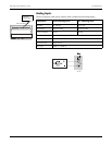
Terminal Cover
Installation Instructions
1. Turn off all power to the meter.
2. Open all PT fuses (or direct voltage input fuses). Close all CT shorting blocks.
3. Ensure that all cables connected to the meter (including those at to the I/O
terminals) are NOT live.
4. For each cover, insert two tabs into the small rectangular openings at either end
of the strip (refer to the diagram below).
5. Optional: you can tamper-proof each terminal strip by inserting a sealing wire
or tag through the holes at the end of the tabs.
6. Close the PT fuses (or direct voltage input fuses), and open the CT shorting
blocks.
7. Turn on power to the meter and verify the correct operation of the unit.
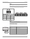
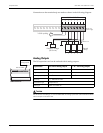
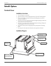
Installation Diagram
Opening where top of tab
will stick through.
Tab (one of four)
Terminal cover for relay
and digital inputs
One of four rectangular
openings
Tamper proofing holes –
insert a sealing wire or tag
through these two holes
(sizes: 0.125” & 0.050”)
Terminal cover
for voltage and
current inputs