


COM1 Port ION 7500 / ION 7600 User’s Guide
Page 164 Chapter 6 - Hardware Reference
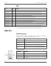
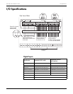
LEDs
1
One or both of the Ethernet LED colors may differ from the standard red and green.
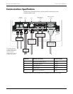
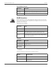
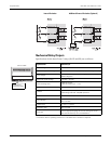
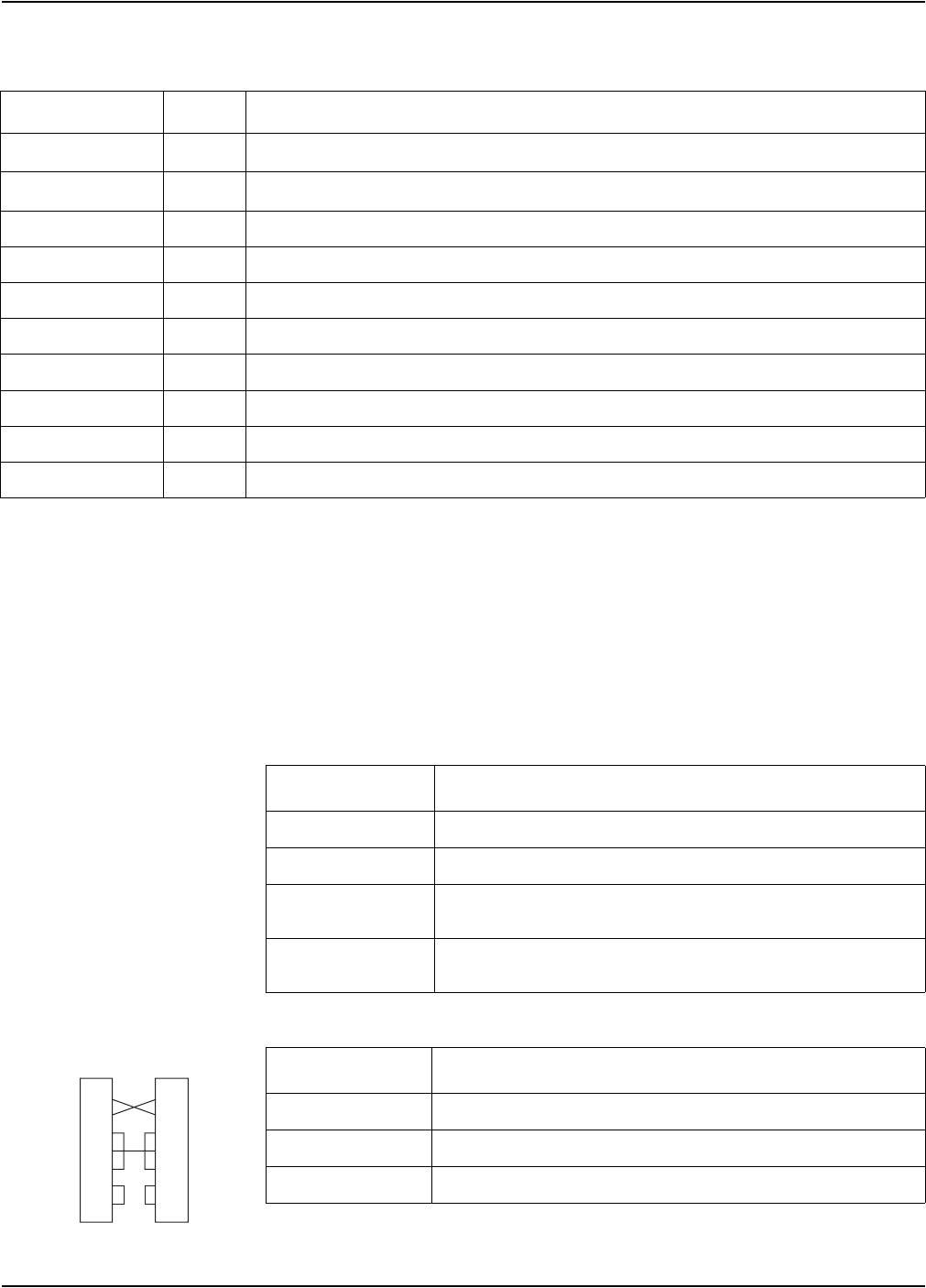
COM1 Port
RS-232 Connections
RS-232 connection is made at the male DB9 connector. The meter acts as a DTE
device in all RS-232 connections. Specifications are as follows:
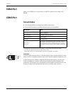
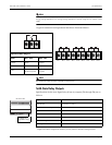
Computer Connections
LED Color Function
Ethernet ACTIVITY
Red
1
Flashes as signals are transmitted and received for both Ethernet 10 Base-T and 10 Base-FL ports
Ethernet LINK
Green
1
On as long as there is an active connection to either the 10 Base-T or 10 Base-FL ports
Internal Modem DCD Green Carrier Detect– Indicates the presence of a carrier signal (active connection to the modem)
Internal Modem RI Green Flashes to when the modem detects rings (Ring Indicator)
COM3 TRANSMIT Red Flashes as signals are transmitted from the COM3 internal modem
COM3 RECEIVE Red Flashes as signals are received on COM3 internal modem
COM2 TRANSMIT Red Flashes as signals are transmitted from the COM2 RS-485 loop
COM2 RECEIVE Red Flashes as signals are received on COM2 RS-485 loop
COM1 TRANSMIT Red Flashes as signals are transmitted from the COM1 RS-232 connection or the COM1 RS-485 loop
COM1 RECEIVE Red Flashes as signals are received on COM1 RS-232 connection or the COM1 RS-485 loop
Specification Value
Baud Rates 300 to 115,200 bps (default is 9,600 bps)
Duplex Full
Supported Protocols
ION, Modbus RTU, DNP 3.0, FACTORY, Iec870-102, GPS: Arbiter,
GPS: TRUE TIME DATUM, EtherGate, ModemGate (default is ION)
Isolation
Optical isolation from all other inputs and outputs (excluding the COM1
RS-485 port); isolation voltage is 750 V peak for 10 seconds @ 60 Hz.
Specification Description
Cable Type Null modem RS-232 cable
Cable Ends DB9 female end for mating with the DB9 male connector on the meter
Max. Cable Length 50 feet (15.2 m)
2
3
4
5
6
7
8
2
3
4
5
6
7
8
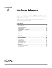
DB9 Null Modem
Wiring Diagram:
DCE
(computer)
DTE
(meter)