


ION 7500 / ION 7600 User’s Guide Disk Simulator (ION 8000 Series)
Custom Front Panel Displays Technical Note Page 205
Disk Simulator (ION 8000 Series)
This ION 8000 Series meter Disk Simulator display simulates the behavior of a
mechanical watt-hour meter indicating power received or delivered by the
direction of the pulse.
Beginning with the ION 8000 Series’ v221 firmware, the meter’s Calibration Pulser
modules support the Disk Simulator feature. The Calibration Pulser module has a
new output register, labeled Disk Position. When pulsed, Disk Position outputs the
accumulated quantity (kWh, kVAh, etc.) associated with its parent module. The
Disk Position outputs accumulated quantities only if the Calibration Pulser module
Port setup register specifies a physical hardware port that is connected to the
meter. If the port is not specified, then the Disk Position output is zero even if there
is a non-zero accumulated quantity.
If the input accumulates positively (i.e. delivered power or energy), and the
Calibration module Int Mode register is set to F
ORWARD, TOTAL or NET, then the
Disk Simulator revolves from left to right. If the input accumulates negatively (i.e.
received power or energy) and the Int Mode register is set to R
EVERSE, then the Disk
Simulator revolves from right to left.
The Calibration module Disk Position output is always a positive numeric value
regardless of the module’s Int Mode setting (F
ORWARD, REVERSE, etc.). Refer to the
online ION Programmer’s Reference for ION module details.
To create a Disk Simulator screen:
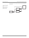
1. Create a new Display module, and choose the type as Disk Simulator.
2. Connect the new Display module’s first input to the Calibration Pulser module’s
Disk Position output that you want to monitor for its pulsing interval.
3. To include the newly added screen to the ALT screen list, connect the Display
module’s Show1 and Show2 inputs to the Scroll module’s last available Trigger
outputs in ALT S
CROLL UP and ALT SCROLL DOWN (respectively).
You can determine the last available Trigger by right-clicking on the output to
discover the Triggers’ owners.
4. Increase the Scroll module’s Wraparound setup register by 1 to include the new
screen.
5. Configure the remaining display settings according to your needs.
Although the Disk Simulator display is intended to show the disk behavior of
mechanical watt-hour meters, this feature can be used to monitor any accumulated
meter quantity over the time. To do this, connect the Display module’s first input
to the meter quantity, and connect the second input to the maximum value that
you expect the displayed quantity to be bounded by (this could be any ION output
register or an External Numeric module register). In this case, (i.e. the Display
module is not connected to a Calibration Pulser module) the Disk Simulator
revolves from left to right.
NOTE
The inputs to the Disk Simulator display are always positive. If the value exceeds the maximum scale value
assigned in the second input, then nothing is displayed except labels and the disk rectangle.