


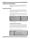

Detailed Module Operation ION 7500 / ION 7600 User’s Guide
Page 222 Digital and Analog I/O Technical Note
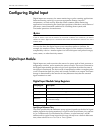
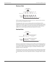
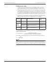
Maximum State
In PULSE mode during maximum operation, the Source input increases so the on-
time and off-time of the pulses are equal.
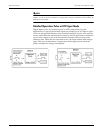
The diagram above shows seven complete pulses for the Calibration Pulser
module in P
ULSE mode, and fourteen transitions for the Calibration Pulser module
in KYZ mode. If the Kt register was set up to send a pulse or KYZ transition for 1.8
energy-hours on each module respectively, then the module in KYZ mode has
output twice as much energy-hours than the module in P
ULSE mode.
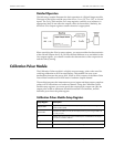
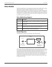
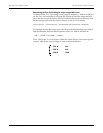
Overload State
If the Source input increases so that an excessive number of state changes appear at
the hardware channel, the Overload Boolean output is turned
ON, and pulsing stops
(i.e. the LED or digital output will remain on) until the energy values return to a
nominal level. The Overload Boolean output is available for Calibration Pulser
modules in P
ULSE or KYZ mode.
The diagram above shows three complete pulses for the Calibration Pulser module
in P
ULSE mode, and six transitions for the Calibration Pulser module in KYZ mode.
For both modules, the Overload output has turned on, causing the LED to remain
lit.
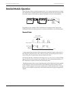
Pulse mode
Pulse Width
(e.g. duration of a lit LED)
Time
KYZ mode
High-Low
transitions
Time
Pulse Width
(e.g. duration of a lit LED)
Excessive transitions (overload
state) causes the LED
to remain lit
Excessive pulsing (overload
state) causes the LED
to remain lit
Pulse mode
KYZ mode
High-Low
transitions