


ION 7500 / ION 7600 User’s Guide Basic Setup Menu
Chapter 2 - Using The Front Panel Page 33
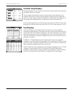
Basic Setup Menu
The Basic Setup menu contains values that typically do not need to be reconfigured
once the meter is put into service. The Basic Setup menu item provides access to the
following power monitoring system settings:
1
Polarities can be normal or inverted.
2
Applicable to meters ordered with the current probe input option.
All Basic Setup menu items are setup registers in the Power Meter module. See the
online ION Programmer’s Reference for details.
The Current Probe phase calibration registers are setup registers in the Factory
module that can be configured in a Telnet or HyperTerminal session. Up to three
separate groups of registers (Factory Default, User Defined 1, and User Defined 2) can
be set up for three different Current Probes. In the Basic Setup menu, the Probe Type
register is used to activate one of those register groups. Only the selected group is
used in the meter’s calculations.
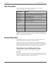
Sub-Menu Register Default Description
PT/CT Setup
Volts Mode 4 Wire Wye The power system’s configuration
PT Primary 120 The Potential Transformer’s primary winding voltage rating for VA, VB, and VC
PT Secondary 120 The Potential Transformer’s secondary winding voltage rating for VA, VB, and VC
CT Primary 5 The Current Transformer’s primary winding current rating for IA, IB, and IC
CT Secondary 5 The Current Transformer’s secondary winding current rating for IA, IB, and IC
V4 Setup
V4 Primary 120 The potential transformer’s primary winding rating on input V4
V4 Secondary 120 The potential transformer’s secondary winding rating on input V4
I4/I5 Setup
I4 Primary 5 The current transformer’s primary winding rating on input I4
I4 Secondary 5 The current transformer’s secondary winding rating on input I4
I5 Primary 5 The current transformer’s primary winding rating on input I5
I5 Secondary 5 The current transformer’s secondary winding rating on input I5
V Polarity
1
VA Polarity Normal The polarity of the potential transformer on VA
VB Polarity Normal The polarity of the potential transformer on VB
VC Polarity Normal The polarity of the potential transformer on VC
V4 Polarity Normal The polarity of the potential transformer on V4
I Polarity
1
IA Polarity Normal The polarity of the current transformer on IA
IB Polarity Normal The polarity of the current transformer on IB
IC Polarity Normal The polarity of the current transformer on IC
I4 Polarity Normal The polarity of the current transformer on I4
I5 Polarity Normal The polarity of the current transformer on I5
Current
Probe
2
Probe Type Factory Default Current Probe Input setting – selects phase angle correction method for I1, I2, I3