


Appendix B Custom Cabling and Optional Connectors
© National Instruments Corporation B-5 6023E/6024E/6025E User Manual
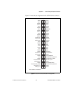
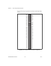
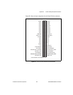
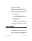
Figure B-3 shows the pin assignments for the 50-pin E Series connector.
Figure B-3. 50-Pin E Series Connector Pin Assignments
GPCTR0_OUT
PFI8/GPCTR0_SOURCE
PFI6/WFTRIG
GPCTR1_OUT
PFI3/GPCTR1_SOURCE
PFI1/TRIG2
EXTSTROBE*
+5 V
DGND
DIO3
DIO2
DIO1
DIO0
AOGND
DAC1OUT
1
AISENSE
ACH7
ACH6
ACH5
ACH4
ACH3
ACH2
ACH1
ACH0
AIGND
FREQ_OUT
PFI7/STARTSCAN
PFI5/UPDATE*
PFI2/CONVERT*
PFI0/TRIG1
SCANCLK
+5 V
PFI9/GPCTR0_GATE
PFI4/GPCTR1_GATE
DIO7
DIO6
DIO5
DIO4
DGND
RESERVED
DAC0OUT
1
ACH15
ACH14
ACH13
ACH12
ACH11
ACH10
ACH9
ACH8
AIGND
49 50
47 48
45 46
43 44
41 42
39 40
37 38
35 36
33 34
31 32
29 30
27 28
25 26
23 24
21 22
19 20
17 18
15 16
13 14
11 12
910
78
56
34
12
1
Not available on the 6023E