


Chapter 4 Signal Connections
6023E/6024E/6025E User Manual 4-10 ni.com
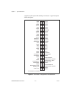
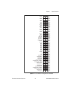
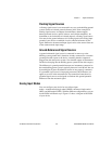
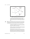
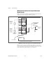
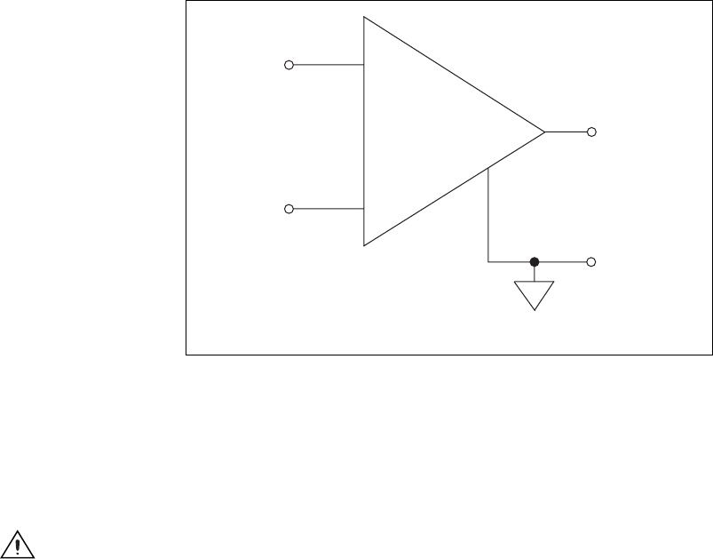
Figure 4-3. Programmable Gain Instrumentation Amplifier (PGIA)
In single-ended mode (RSE and NRSE), signals connected to ACH<0..15>
are routed to the positive input of the PGIA. In DIFF mode, signals
connected to ACH<0..7> are routed to the positive input of the PGIA, and
signals connected to ACH<8..15> are routed to the negative input of the
PGIA.
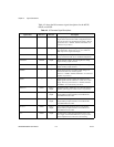
Caution
Exceeding the DIFF and common-mode input ranges distorts your input signals.
Exceeding the maximum input voltage rating can damage the device and the computer.
National Instruments is not liable for any damages resulting from such signal connections.
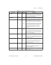
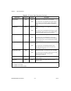
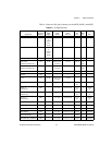
The maximum input voltage ratings are listed in the Protection column of Table 4-3.
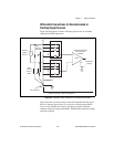
In NRSE mode, the AISENSE signal connects internally to the negative
input of the PGIA when their corresponding channels are selected. In DIFF
and RSE modes, AISENSE is left unconnected.
AIGND is an analog input common signal that routes directly tothe ground
connection point onthe devices. You can usethis signal fora general analog
ground connection point to your device if necessary.
The PGIA applies gain and common-mode voltage rejection and presents
high input impedance to the analog input signals connected to your device.
Signals are routed to the positive and negative inputs of the PGIA through
input multiplexers on the device. The PGIA converts two input signals to a
signal that is the difference between the two input signals multiplied by the
-
Programmable
Gain
Instrumentation
Amplifier
-
Measured
Voltage
V
m
+
+
PGIA
V
in+
V
in-
V
m
=[V
in+
-V
in-
]* Gain