


Chapter 4 Signal Connections
© National Instruments Corporation 4-39 6023E/6024E/6025E User Manual
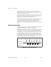
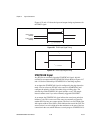
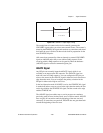
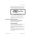
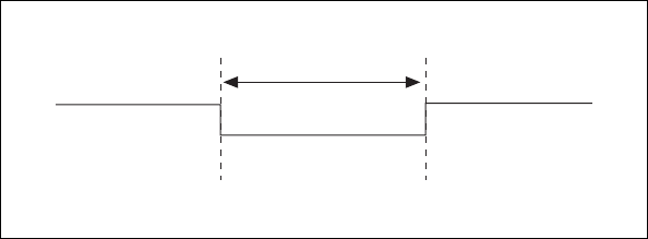
Figure 4-28. CONVERT* Output Signal Timing
The sample interval counter on the device normally generates the
CONVERT* signal unless you select some external source. The counter is
started by the STARTSCAN signal and continues to count down and reload
itself until the scan is finished. It then reloads itself in preparation for the
next STARTSCAN pulse.
A/D conversions generated by either an internal or external CONVERT*
signal are inhibited unless they occur within a DAQ sequence. Scans
occurring within a DAQ sequence can be gated by either the hardware
(AIGATE) signal or software command register gate.
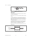
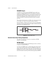
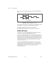
AIGATE Signal
Any PFI pin can externally input the AIGATE signal, which is not
available as an output on the I/O connector. The AIGATE signal can
mask off scans in a DAQ sequence. You can configure the PFI pin you
select as the source for the AIGATE signal in either the level-detection or
edge-detection mode. You can configure the polarity selection for the
PFI pin for either active high or active low.
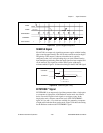
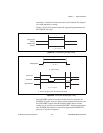
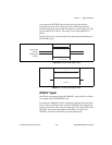
In the level-detection mode if AIGATE is active, the STARTSCAN signal
is masked off and no scans can occur. In the edge-detection mode, the first
active edge disables the STARTSCAN signal, and the second active edge
enables STARTSCAN.
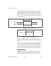
The AIGATE signal can neither stop a scan in progress nor continue a
previously gated-off scan; in other words, once a scan has started, AIGATE
does not gate off conversions until the beginning of the next scan and,
conversely, if conversions are gated off, AIGATE does not gate them back
on until the beginning of the next scan.
t
w
t
w
= 50-150 ns