


Chapter 4 Signal Connections
© National Instruments Corporation 4-31 6023E/6024E/6025E User Manual
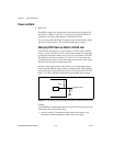
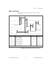
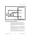
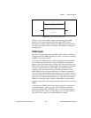
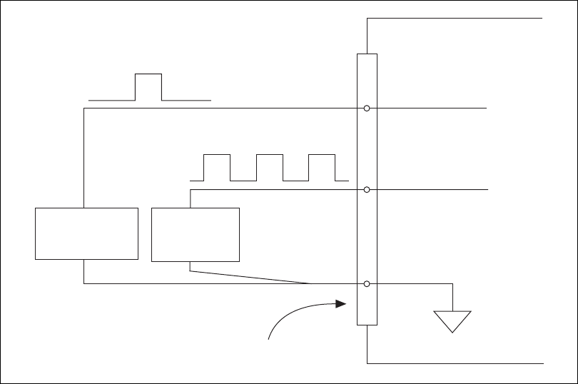
Figure 4-16. Timing I/O Connections
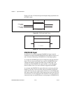
Programmable Function Input Connections
There are a total of 13 internal timing signals that you can externally
control from the PFI pins. The source for each of these signals is
software-selectable from any of the PFIs when you want external control.
This flexible routing scheme reduces the need to change the physical
wiring to the device I/O connector for different applications requiring
alternative wiring.
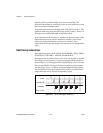
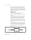
You can individually enable each of the PFI pins to output a specific
internal timing signal. For example, if you need the CONVERT* signal as
an output on the I/O connector, software can turn on the output driver for
the PFI2/CONVERT* pin. Be careful not to drive a PFI signal externally
when it is configured as an output.
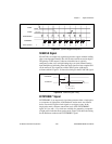
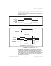
As an input, you can individually configure each PFI pin for edge or level
detection and for polarity selection, as well. You can use the polarity
selection for any of the 13 timing signals, but the edge or level detection
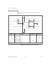
TRIG1
Source
DGND
PFI0/TRIG1
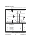
PFI2/CONVERT*
CONVERT*
Source
I/O Connector