


Chapter 4 Signal Connections
6023E/6024E/6025E User Manual 4-46 ni.com
GPCTR1_SOURCE Signal
Any PFI pin can externally input the GPCTR1_SOURCE signal, which is
available as an output on the PFI3/GPCTR1_SOURCE pin. As an input,
the GPCTR1_SOURCE signal is configured in the edge-detection mode.
You can select any PFI pin as the source for GPCTR1_SOURCE and
configure the polarity selection for either rising or falling edge.
As an output, the GPCTR1_SOURCE monitors the actual clock connected
to general-purpose counter 1. This is true even if the source clock is
externally generated by another PFI. This output is set to high impedance
at startup.
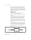
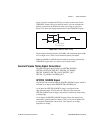
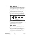
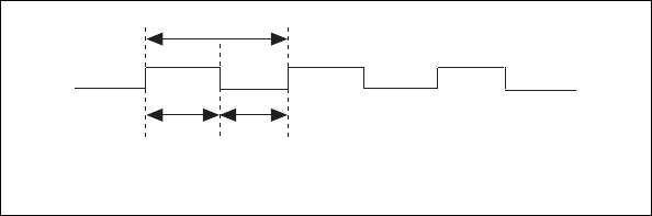
Figure 4-38 shows the timing requirements for the GPCTR1_SOURCE
signal.
Figure 4-38. GPCTR1_SOURCE Signal Timing
The maximum allowed frequency is 20 MHz, with a minimum pulse width
of 23 ns high or low. There is no minimum frequency limitation.
The 20 MHz or 100 kHz timebase normally generates the
GPCTR1_SOURCE unless you select some external source.
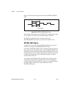
GPCTR1_GATE Signal
Any PFI pin can externally input the GPCTR1_GATE signal, which is
available as an output on the PFI4/GPCTR1_GATE pin.
As an input, the GPCTR1_GATE signal is configured in edge-detection
mode. You can select any PFI pin as the source for GPCTR1_GATE and
configure the polarity selection for either rising or falling edge. You can use
the gate signal in a variety of different applications to perform such actions
as starting and stopping the counter, generating interrupts, saving the
counter contents, and so on.
t
p
t
w
t
w
t
p
t
w
= 50 ns minimum
= 23 ns minimum