


Chapter 4 Signal Connections
6023E/6024E/6025E User Manual 4-24 ni.com
Power-up State
♦ 6025E only
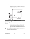
The 6025E contains bias resistors that control the state of the digital I/O
lines PA<0..7>,PB<0..7>,PC<0..7> at power up. Each digital I/O line is
configured as an input, pulled high by a 100 kΩ bias resistor.
You can change individual lines from pulled up to pulled down by adding
your own external resistors. This section describes the procedure.
Changing DIO Power-up State to Pulled Low
Each DIO line is pulled to V
cc
(approximately +5 VDC) with a 100 kΩ
resistor. To pull a specific line low, connect between that line and ground
a pull-down resistor (R
L
) whose value gives you a maximum of 0.4 VDC.
The DIO lines provide a maximum of 2.5 mA at 3.7 V in the high state.
Using the largest possible resistor ensures that you do not use more current
than necessary to perform the pull-down task.
However, make sure the value of the resistor is not so large that leakage
current from the DIO line along with the current from the 100 kΩ pull-up
resistor drivesthe voltageat the resistorabove aTTL-low level of0.4 VDC.
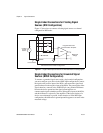
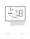
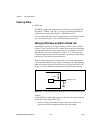
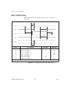
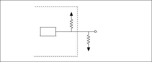
Figure 4-12 shows the DIO configuration for high DIO power-up state.
Figure4-12. DIO ChannelConfiguredfor HighDIO Power-upState withExternalLoad
Example
A given DIO line is pulled high at power up. To pull it low onpower upwith
an external resistor, follow these steps:
1. Install a load (R
L
). Remember that the smaller the resistance, the
greater the current consumption and the lower the voltage.
Device
Digital I/O Line
82C55
100 k
GND
R
L
+5 V