


Chapter 4 Signal Connections
© National Instruments Corporation 4-45 6023E/6024E/6025E User Manual
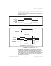
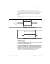
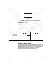
Figure 4-36.
GPCTR0_GATE Signal Timing in Edge-Detection Mode
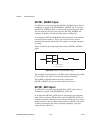
GPCTR0_OUT Signal
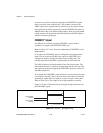
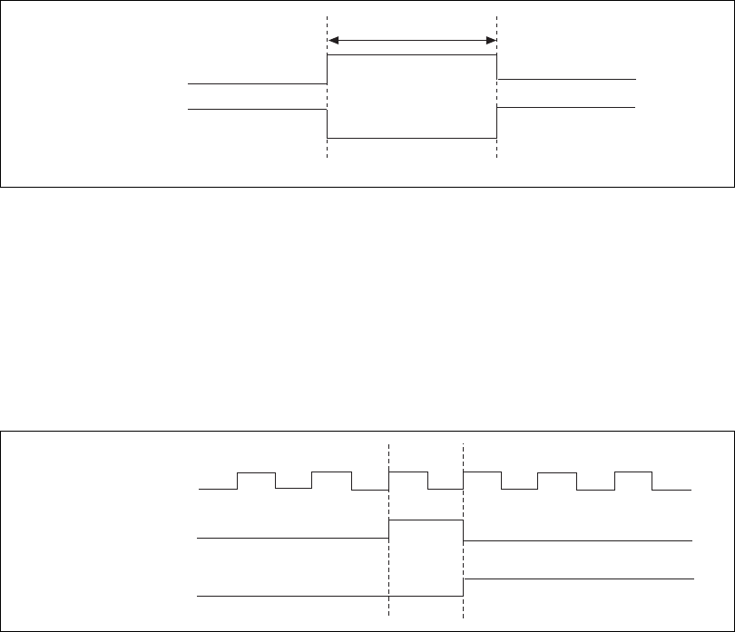
This signal is available only as an output on the GPCTR0_OUT pin. The
GPCTR0_OUT signal reflects the terminal count (TC) of general-purpose
counter 0. You have two software-selectable output options—pulse on TC
and toggle outputpolarity onTC. The output polarityis software-selectable
for both options. This output is set to high impedance at startup.
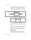
Figure 4-37 shows the timing of the GPCTR0_OUT signal.
Figure 4-37.
GPCTR0_OUT Signal Timing
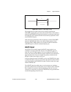
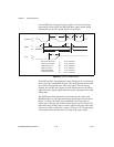
GPCTR0_UP_DOWN Signal
This signal can be externally input on the DIO6 pin and is not available as
an output on the I/O connector. The general-purpose counter 0 countsdown
when this pin is at a logic low and count up when it is at a logic high. You
can disable this input so that software can control the up-down
functionality and leave the DIO6 pin free for general use.
Rising-Edge
Polarity
Falling-Edge
Polarity
t
w
t
w
= 10 ns minimum
GPCTR0_SOURCE
GPCTR0_OUT
GPCTR0_OUT
(Toggle Output on TC)
(Pulse on TC)
TC