


Chapter 4 Signal Connections
© National Instruments Corporation 4-35 6023E/6024E/6025E User Manual
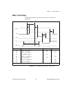
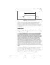
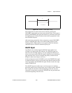
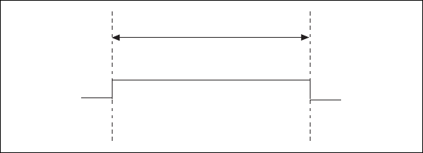
Figure 4-22.
TRIG1 Output Signal Timing
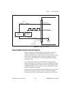
The device also uses the TRIG1 signal to initiate pretriggered DAQ
operations. In most pretriggered applications, the TRIG1 signal is
generated by a software trigger. Refer to the TRIG2 signal description for
a complete description of the use of TRIG1 and TRIG2 in a pretriggered
DAQ operation.
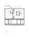
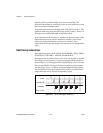
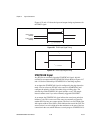
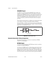
TRIG2 Signal
Any PFI pin can externally input the TRIG2 signal, which is available as
an output on the PFI1/TRIG2 pin. Refer to Figure 4-18 for the relationship
of TRIG2 to the DAQ sequence.
As an input, the TRIG2 signal is configured in the edge-detection mode.
You can select any PFI pin as the source for TRIG2 and configure the
polarity selection for either rising or falling edge. The selected edge of the
TRIG2 signal initiates the posttriggered phase of a pretriggered acquisition
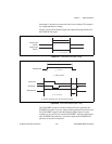
sequence. In pretriggered mode, the TRIG1 signal initiates the data
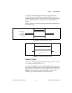
acquisition. The scan counter indicates the minimum number of scans
before TRIG2 can be recognized. After the scan counter decrements to
zero, it is loaded with the number of posttrigger scans to acquire while the
acquisition continues. The device ignores the TRIG2 signal if it is asserted
prior to the scan counter decrementing to zero. After the selected edge of
TRIG2 is received, the device acquires a fixed number of scans and the
acquisition stops. This mode acquires data both before and after receiving
TRIG2.
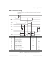
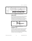
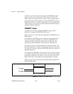
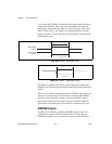
As an output, the TRIG2 signal reflects the posttrigger in a pretriggered
acquisition sequence. This is true even if the acquisition is externally
triggered by another PFI. The TRIG2 signal is not used in posttriggered
data acquisition. The output is an active high pulse with a pulse width of
50 to 100 ns. This output is set to high impedance at startup.
t
w
t
w
= 50-100 ns