


Chapter 4 Signal Connections
© National Instruments Corporation 4-5 6023E/6024E/6025E User Manual
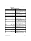
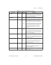
SCANCLK DGND Output scan clock—this pin pulses once for each A/D conversion
in scanning mode when enabled. The low-to-high edge
indicates when the input signal can be removed from the
input or switched to another signal.
EXTSTROBE* DGND Output External strobe—you can togglethis output under software
control tolatch signalsortrigger eventson externaldevices.
PFI0/TRIG1 DGND Input
Output
PFI0/Trigger 1—as an input, this is one of the
programmable function inputs (PFIs). PFI signals are
explainedin the TimingConnectionssectioninthischapter.
As an output, this is the TRIG1 (AI start trigger) signal.
In posttrigger data acquisition sequences, a low-to-high
transition indicates the initiation of the acquisition
sequence. In pretrigger applications, a low-to-high
transition indicates the initiation of the pretrigger
conversions.
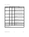
PFI1/TRIG2 DGND Input
Output
PFI1/Trigger 2—as an input, this is one of the PFIs.
As an output, this is the TRIG2 (AI stop trigger) signal. In
pretrigger applications, a low-to-high transition indicates
the initiation of the posttrigger conversions. TRIG2 is not
used in posttrigger applications.
PFI2/CONVERT* DGND Input
Output
PFI2/Convert—as an input, this is one of the PFIs.
As an output, this is the CONVERT* (AI convert) signal.
A high-to-low edge on CONVERT* indicates that an A/D
conversion is occurring.
PFI3/GPCTR1_SOURCE DGND Input
Output
PFI3/Counter 1Source—as aninput,this isone ofthe PFIs.
As an output, this is the GPCTR1_SOURCE signal. This
signal reflects the actual source connected to the
general-purpose counter 1.
PFI4/GPCTR1_GATE DGND Input
Output
PFI4/Counter 1 Gate—as an input, this is one of the PFIs.
Asanoutput, thisis theGPCTR1_GATEsignal.Thissignal
reflects the actual gate signal connected to the
general-purpose counter 1.
GPCTR1_OUT DGND Output Counter 1 Output—this output is from the general-purpose
counter 1 output.
Table 4-2. I/O Connector Signal Descriptions (Continued)
Signal Name Reference Direction Description