


Chapter 4 Signal Connections
© National Instruments Corporation 4-37 6023E/6024E/6025E User Manual
deasserted t
off
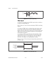
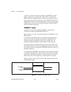
after the last conversion in the scan is initiated. This output is
set to high impedance at startup.
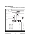
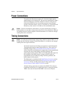
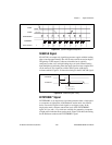
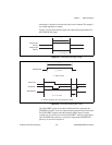
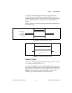
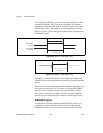
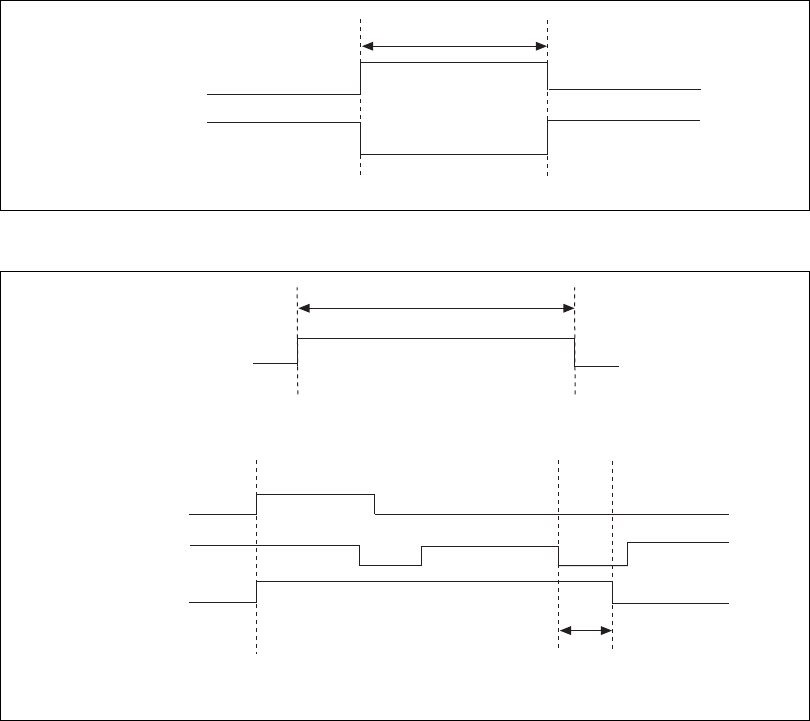
Figures 4-25 and 4-26 show the input and output timing requirements for
the STARTSCAN signal.
Figure 4-25.
STARTSCAN Input Signal Timing
Figure 4-26.
STARTSCAN Output Signal Timing
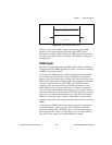
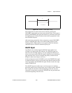
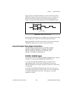
The CONVERT* pulses are masked off until the device generates the
STARTSCAN signal. If you are using internally generated conversions, the
first CONVERT* appears when the onboard sample interval counter
reaches zero. If you select an external CONVERT*, the first external pulse
after STARTSCAN generates a conversion. Separate the STARTSCAN
pulses by at least one scan period.
Rising-Edge
Polarity
Falling-Edge
Polarity
t
w
t
w
= 10 ns minimum
t
w
= 50-100 ns
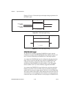
a. Start of Scan
t
off
t
off
= 10 ns minimum
Start Pulse
CONVERT*
STARTSCAN
STARTSCAN
b. Scan in Progress, Two Conversions per Scan
t
w