


Chapter 3 Hardware Overview
6023E/6024E/6025E User Manual 3-8 ni.com
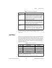
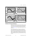
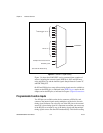
Figure 3-4. CONVERT* Signal Routing
Figure 3-4 shows that CONVERT* can be generated from a number of
sources, including the external signals RTSI<0..6> (PCI and PXI buses
only) and PFI<0..9> and the internal signals Sample Interval Counter TC
and GPCTR0_OUT.
On PCI and PXI devices, many of these timing signals are also available as
outputs on the RTSI pins, as indicated in the RTSI Triggers sectioninthis
chapter, and on the PFI pins, as indicated in Chapter 4, Signal Connections.
Programmable Function Inputs
Ten PFI pins are available on the device connector as PFI<0..9> and
connect to the internal signal routing multiplexer of the device for each
timing signal. Software can select any one of the PFI pins as the external
source for a given timing signal. It is important to note that you can use any
of the PFI pins as an input by any of the timing signals and that multiple
timing signals can use the same PFI simultaneously. This flexible routing
†
RTSITrigger <0..6>
PFI<0..9>
CONVERT*
Sample Interval Counter TC
GPCTR0_OUT
†
PCI and PXI Buses Only